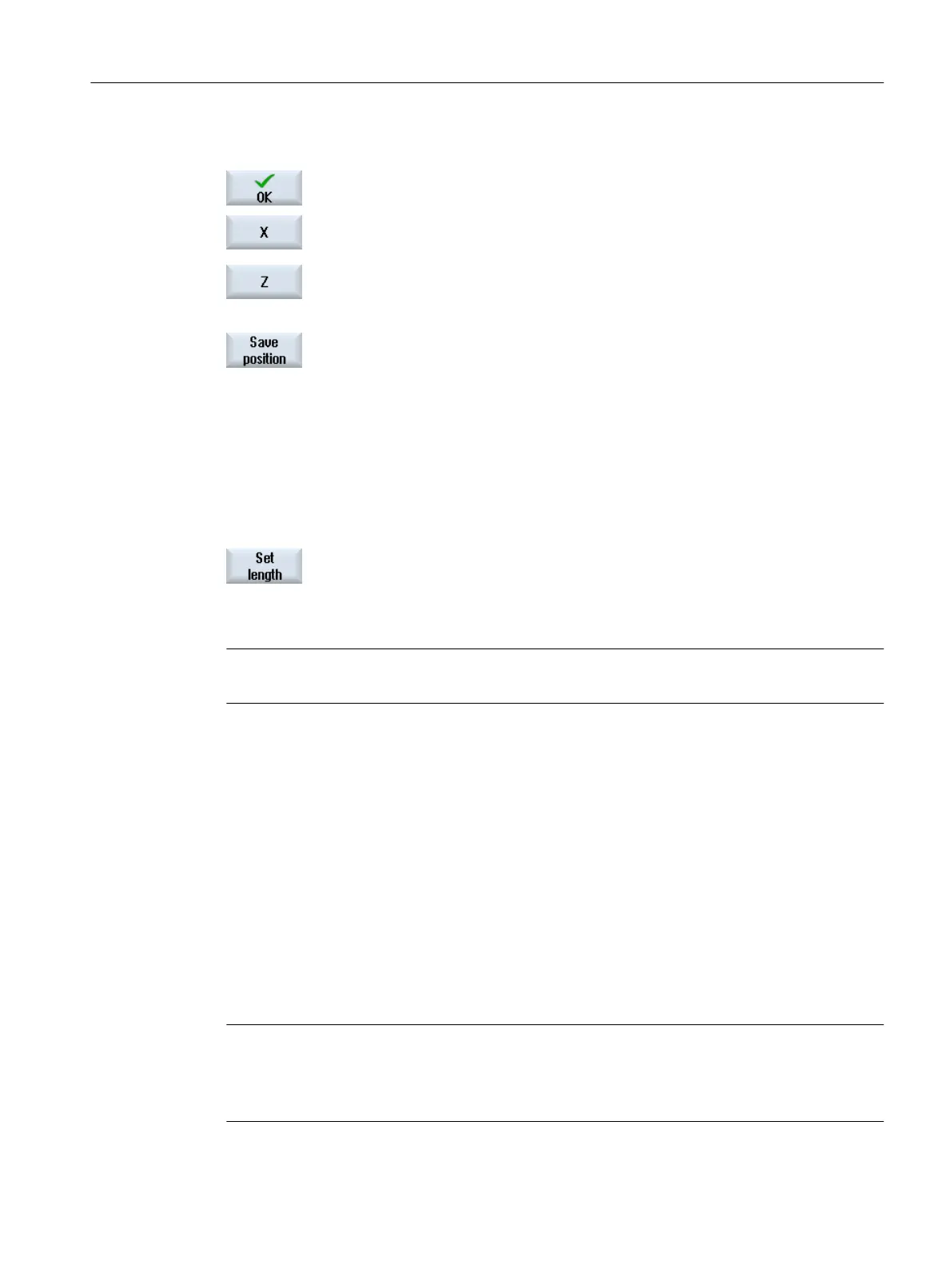
6. Press the "OK" softkey.
The tool is transferred into the window "Measure: Length manual".
7. Press the "X" or "Z" softkey, depending on which tool length you want to
measure.
8. Scratch the required edge using the tool.
9. If you do not wish to keep the tool at the workpiece edge, then press the
"Save position" softkey.
The tool position is saved and the tool can be retracted from the work‐
piece. For instance, this can be practical if the workpiece diameter still
has to be subsequently measured.
If the tool can remain at the workpiece edge, then after scratching you
can directly continue with step 11.
10. Enter the position of the workpiece edge in X0 or Z0.
If no value is entered for X0 or Z0, the value is taken from the actual value
display.
11. Press the "Set length" softkey.
The tool length is calculated automatically and entered in the tool list.
Whereby the cutting edge position and tool radius or diameter are auto‐
matically taken into consideration as well.
Note
Tool measurement is only possible with an active tool.
4.5.10 Manually measuring a turning tool using a tool probe (for milling/turning machine)
During automatic measuring, you determine the tool dimensions in the X and Z axes using a
probe.
You have the possibility of measuring a tool using a tool holder that can be oriented (tool carrier,
swivel).
The function "Measure with orientable tool carrier" is implemented for lathes with a swivel axis
around Y and associated tool spindle. The swivel axis can be used to align the tool at the X/Z
level. The swivel axis can assume any position around Y to measure turning tools. Multiples
of 90° are permitted for milling and drilling tools. Multiples of 180° are possible when positioning
the tool spindle.
Note
Milling/turning machines with a B axis (only 840D sl)
For milling/turning machines with a B axis, execute the tool change and alignment in the T, S,
M window before performing the measurement.
Setting up the machine
4.5 Measure tool
Milling
Operating Manual, 08/2018, 6FC5398-7CP41-0BA0 109

 Loading...


