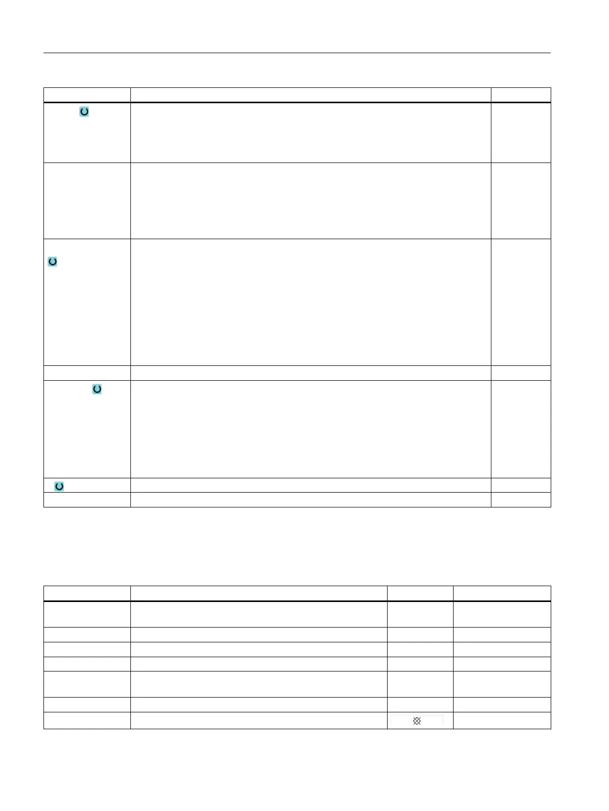
Parameter Description
Thread Direction of rotation of the thread
● Right-hand thread
● Left-hand thread
(only in mode "without compensating chuck")
Selection Selection of table value: e.g.
● M3; M10; etc. (ISO metric)
● W3/4; etc. (Whitworth BSW)
● G3/4; etc. (Whitworth BSP)
● 1" - 8 UNC; etc. (UNC)
P
Pitch ...
● In MODULUS: MODULUS = Pitch/π
● In turns per inch: Used with pipe threads, for example.
When entered per inch, enter the integer number in front of the decimal point in the
first parameter field and the figures after the decimal point as a fraction in the second
and third field.
● In mm/rev
● In inch/rev
The pitch is determined by the tool being used.
MODULUS
Turns/"
mm/rev
in/rev
S Spindle speed - (only for tapping without compensating chuck).
Machining (not
for "with compen‐
sating chuck")
The following machining operations can be selected:
● One cut
The thread is drilled in one cut without interruption.
● Chip breaking
The drill is retracted by the retraction amount V2 for chip breaking.
● Swarf removal
The drill is retracted from the workpiece for swarf removal.
D 1st drilling depth (abs) or 1st drilling depth referred to Z0 (inc) mm
SR Spindle speed for retraction - (only for "without compensating chuck"). rpm
Hidden parameters
The following parameters are hidden. They are pre-assigned fixed values or values that can
be adjusted using setting data.
Parameter Description Value Can be set in SD
PL Machining plane Defined in MD
52005
SC Safety clearance 1 mm x
Table Thread table selection Without
αS Starting angle offset 0°
Retraction Without retraction distance after each machining step - (for
chip breaking only)
Automatic
DT Dwell time at final drilling depth 0.6 s x
SDE Direction of rotation after end of cycle
Programming technological functions (cycles)
10.1 Drilling
Milling
402 Operating Manual, 08/2018, 6FC5398-7CP41-0BA0

 Loading...


