SIRIUS 3RT2 contactors/contactor assemblies
2.4 Configuration
SIRIUS Innovations
System Manual, 01/2011, A8E56203870002-03
141
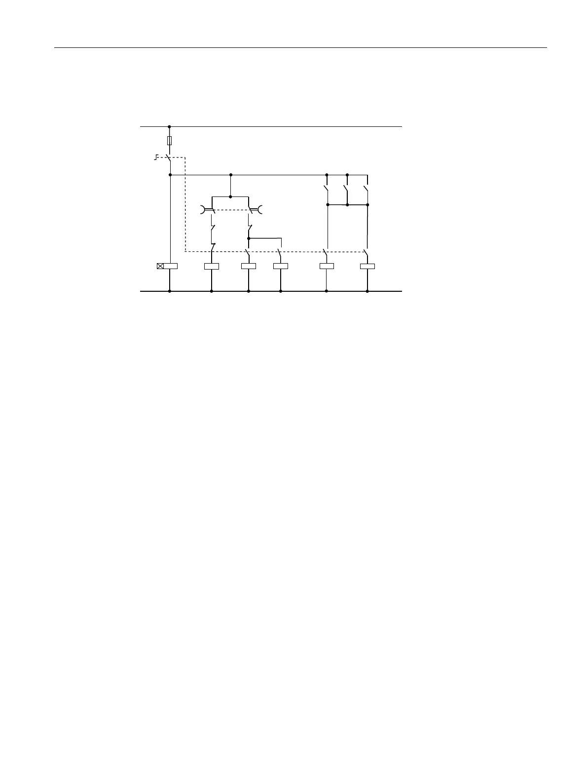
Control circuit
The diagram below shows the control circuit for the main circuit depicted above.
'HOWD
&&:
'HOWD
&:
/LQH
&&:
7LPLQJ
UHOD\
6WDU
FRQWDFWRU
'HOWD
&&:
'HOWD
&:
/LQH
&&:
/LQH
&:
/LQH
&:
//
1/
<
7
<
Figure 2-17 Control circuit of the contactor assembly for star-delta (wye-delta) start
2.4.11 Using long control cables
Malfunctions caused by long control cables
If long control cables are required for the control circuits of contactors or relays, malfunctions
may occur during switching under certain conditions. As a result of these malfunctions, the
contactors may no longer be able to switch on or off.
Switching on
Due to the voltage drop in long control cables, the control voltage applied to the contactor
may fall below the threshold value at which the contactor switches on. This affects both DC-
and AC-operated contactors.
The following counter-measures can be taken:
● Changed circuit topology to allow for the application of shorter control cables.
● Increased conductor cross-section.
● Increased control voltage.
● Use of a contactor whose magnet coil has a lower closing power.
Calculation of the maximum cable length:
The maximum permissible simple cable length l
zul
can be roughly calculated using the
equations given below.
 Loading...