SIRIUS 3RU2/3RB3 overload relays
5.6 Mounting
SIRIUS Innovations
508 System Manual, 01/2011, A8E56203870002-03
5.6 Mounting
5.6.1 Mounting options
Mounting options for the 3RU21
3RU21 thermal overload relays are matched to 3RT contactors in terms of their electrical
and mechanical features. As a result, direct mounting can be achieved easily. Alternatively,
the devices are suitable for stand-alone assembly.
Mounting options for the 3RB30/3RB31
3RB30/3RB31 solid-state overload relays are suitable for space-saving, direct mounting onto
3RT contactors as well as for stand-alone assembly.
5.6.2 Minimum clearances and mounting position
Minimum clearance
A minimum lateral clearance of > 6 mm must be maintained from grounded parts.
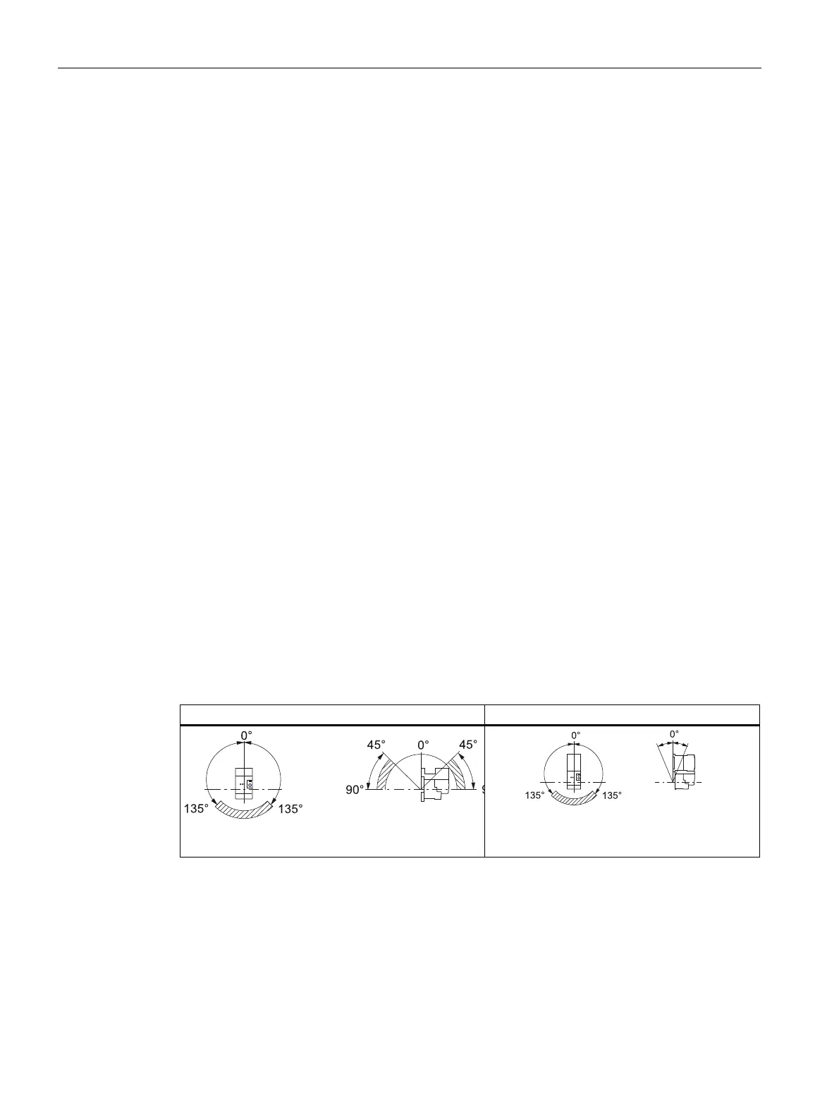
Mounting position for 3RU21 thermal overload relay
The diagrams below illustrate the permissible mounting positions for contactor mounting and
stand-alone assembly in the case of 3RU21 thermal overload relays.
Table 5- 13 Permissible mounting positions for the 3RU21
Overload relay, stand-alone assembly Contactor + overload relay
,
H
[ ,
,
H
[
,
H
[
rr
The set value is 1.1 times the motor current for a mounting position in the hatched area.
Mounting position for 3RB30/3RB31 solid-state overload relay
For 3RB30/3RB31 solid-state overload relays any mounting position can be chosen as
required.
 Loading...