SIRIUS 3RF34 solid-state switching devices
3.10 Accessories
SIRIUS Innovations
System Manual, 01/2011, A8E56203870002-03
349
3.10.3.2 Mounting/Disassembly
Mounting/disassembly of the link module for the motor starter protector
Before a motor starter protector can be attached to the solid-state contactor/solid-state
reversing contactor, a link module must be installed between the two devices. The insulated
design of the devices means that grounding is not required.
Side-by-side mounting facilitates the installation of several devices one next to the other. The
devices can be mounted with screws or snapped onto DIN rails.
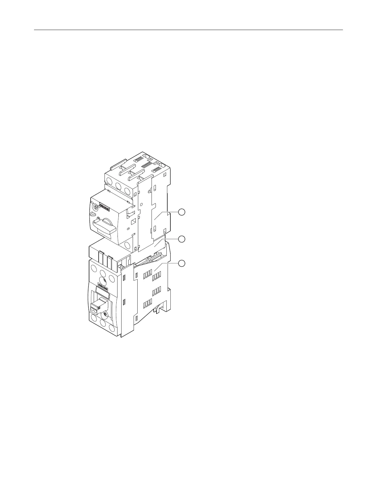
The example in the figure below illustrates the mounting of the link module on a solid-state
contactor.
1 Motor starter protector
2 Link module
3 Solid-state contactor
Figure 3-17 Setup: Motor starter protector, link module, solid-state contactor
 Loading...