SIRIUS 3RT2 contactors/contactor assemblies
2.7 Accessories
SIRIUS Innovations
System Manual, 01/2011, A8E56203870002-03
201
Making capacity/breaking capacity
The table below specifies the magnitude of a contactor's making and breaking capacities, in
relation to the load currents for two or three current paths connected in parallel:
Table 2- 53 Parallel switching connections: Making capacity/breaking capacity
3-pole switching 2 current paths in
parallel
3 current paths in
parallel
4 current paths in
parallel
,
H
,
H
,
H
,
H
,
H
,
H
,
ಬ
H
,
H
,
ಬಬ
H
,
H
,
ಬಬ
H
,
H
Making capacity 12 x I
e
(utilization
category AC-4)
, ಿHຘ
, ಿ H
ຘ
, ಿಿ Hຘ
,ಿಿH
ຘ
, ಿಿ Hຘ
, ಿ ಿ H
ຘ
Breaking capacity 10 x I
e
(utilization
category
AC-4)
, ಿ eຘ
,ಿHຘ
, ಿಿ Hຘ
, ಿ ಿ Hຘ
, ಿಿ Hຘ
,ಿಿHຘ
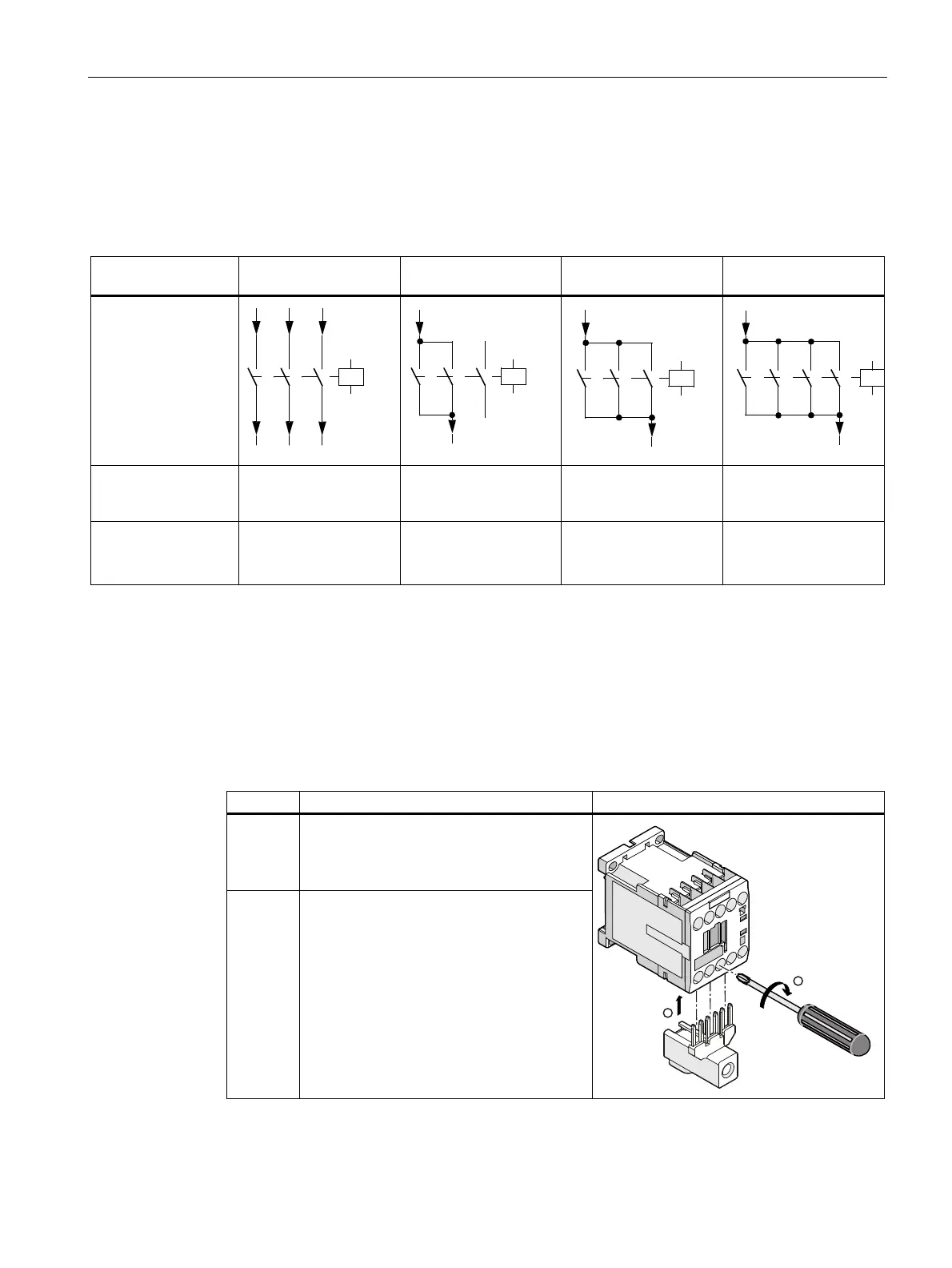
2.7.16.3 Mounting
The parallel switching connectors of size S00 can all be reduced by one pole. The illustration
below shows an example of how to mount the 3-pole parallel switching connector with
connection terminal to a contactor of size S00.
Table 2- 54 Mounting the 3-pole parallel switching connector with connection terminals
Step Operating instruction Image
1 Insert the pins of the parallel switching
connector into the contactor's terminal
openings from below until they are securely
in position.
2 Screw the parallel switching connector tight
with a screwdriver.
 Loading...