SIRIUS 3RV2 motor starter protectors
4.8 Operation
SIRIUS Innovations
404 System Manual, 01/2011, A8E56203870002-03
4.8 Operation
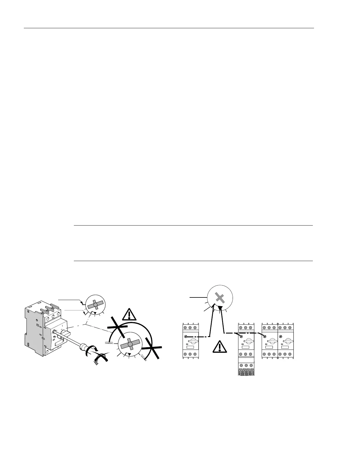
4.8.1 Setting the current
Procedure
Use a screwdriver to set the load's rated current (current setting) I
e
on the scale on the motor
starter protector.
In the context of this setting, a distinction is made between two fundamental designs:
1. Stand-alone assembly: No directly mounted contactor and clearance of at least 10 mm to
left and right.
2. Side-by-side design: Directly mounted contactor or clearance to left and right of less than
10 mm (commonly used design).
Note the two possible setting marks on the adjusting knob:
● Dash marking: Setting mark for the motor starter protector in stand-alone design.
● Triangular marking: Setting mark for the motor starter protector in side-by-side design.
In both cases you can use the full current range up to the scale mark at the top for size
S00/S0 motor starter protectors at ambient temperatures of up to + 60 °C.
Note
Max. ambient temperature at 36 A/40 A
In the case of motor starter protectors with 36 A/40 A the maximum permissible ambient
temperature is 40 °C.
Set the relevant setting mark (dash or triangle) to the load current.
360 ° ok
max. + 60 °C
max. + 70 °C
1.4
1.1
1.6 A max
,
H
$
Figure 4-5 Making the current setting I
e
 Loading...