SIRIUS 3RV2 motor starter protectors
4.6 Mounting
SIRIUS Innovations
System Manual, 01/2011, A8E56203870002-03
401
4.6 Mounting
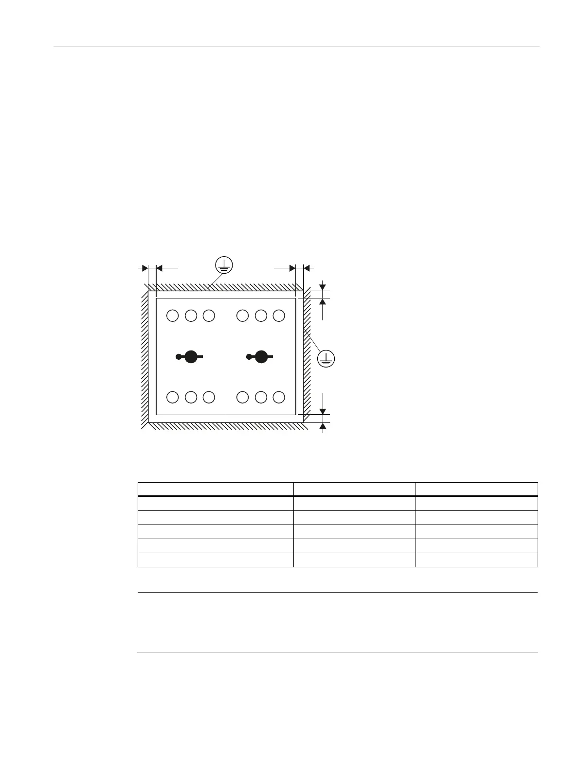
4.6.1 Standard mounting
4.6.1.1 Minimum clearances and mounting position
Minimum clearances
The following clearances from grounded or live parts and from cable ducts made of molded
plastic must be observed in compliance with IEC 60947-2 when mounting motor starter
protectors.
/
=
59 59
=
<<
/ /
7 7 7 7 7 7
/ / /
Figure 4-3 Clearances from grounded or live parts
Table 4- 7 Installation guidelines for motor starter protectors
U
e
[V] Y [mm] Z [mm]
240 30 9
400 30 9
440 30 9
500 30 9
690 50 / 70
1)
30
1)
Up to and including the setting range of 32 A, the required clearance above and below is 50 mm;
for the 36/40 A setting range, the clearance is 70 mm.
Note
Terminal block type E
In conjunction with type E terminal block 3RV2928-1H the applicable lateral clearance is
30 mm for all voltages.
Mounting position
The mounting position of 3RV2 motor starter protectors can be selected at will.
 Loading...