SIRIUS 3RA28 function modules for mounting on 3RT2 contactors
7.7 Connection
SIRIUS Innovations
System Manual, 01/2011, A8E56203870002-03
671
7.7.1.2 Connecting the solid-state time-delay auxiliary switch
Connection types
The solid-state time-delay auxiliary switch is connected via removable terminals with the
following connection options:
● Screw-type
● Spring-loaded
Connection
The Connection systems (Page 74) section of the chapter titled System overview describes
how the screw-type/spring-loaded connections are made.
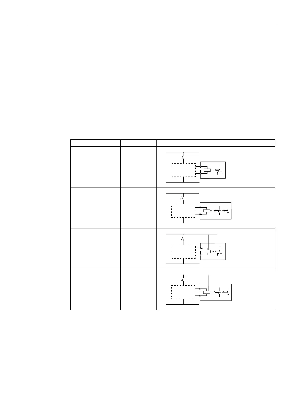
Designation Terminal Circuit diagram
3RA2813-.AW10
ON-delay, 1 CO
contact
18 NO
15 NC
16 NC
Q
L1(+)
N(-)
S1
A2
A1
16
18
15
3RA2813-.FW10
ON-delay, 1 NC
contact/1 NO contact
27 NO
28 NO
35 NC
36 NC
Q
L1(+)
N(-)
S1
A2
A1
36
28
27 35
3RA2814-.AW10
OFF-delay, 1 CO
contact
18 NO
15 NC
16 NC
A3 (+)
Q
L1(+)
N(-)
S1
A3
A2
A1 = B1
16
18
15
3RA2814-.FW10
OFF-delay with
auxiliary voltage, 1 NC
contact/1 NO contact
27 NO
28 NO
35 NC
36 NC
A3 (+)
Q
S1
L1(+)
N(-)
A3
A2
A1 = B1
36
28
27 35
 Loading...