203
For details about detents, see “Detents” (page 196).
To return parameters to the initial settings
The parameters return to the initial status saved data
se
tting values.
The operation must be performed separately for global
spac
e and local space.
For details about initial status, see “Setting Startup”
(page 359).
To return three-dimensional parameters to the initial
setti
ngs:
Press the [Clear 3D Parameter] button.
To return all DME parameters to the initial settings:
Press the [Clear All Parameters] button.
Graphics Display
Overview
This function allows you to display wire frames,
coordinate axes, and a grid over a DME image.
You can configure the following kinds of graphics.
Do not use the graphics display function while on-air, as
i
mages in a DME, clip player, or multi viewer may
become distorted while in use.
Wire frame
Places a wire frame around the image. This allows you to
check
the position and size of the image.
When a Shadow global effect is set, a shadow frame is
di
splayed.
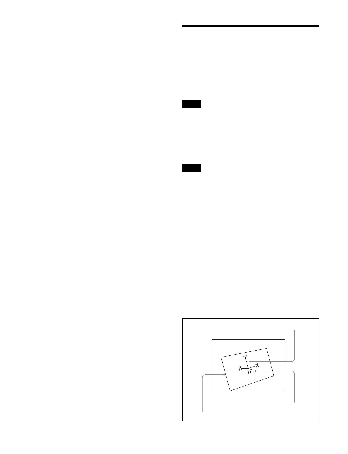
Coordinate axes
Displays three-dimensional coordinates in local space or
gl
obal space. This allows you to check the origin and the
directions of the X-axis, Y-axis, and Z-axis.
Channel ID
Displays the channel number. This allows you to check
t
he channel being used.
Channel IDs are displayed differently in local space and
gl
obal space.
Local space: The channel number is displayed along with
“F”
(Front) or “B” (Back) indicating the side of the
wire frame. For example, “1F” indicates that channel
1 is being used at the front in local space.
Global space: The channel number is displayed along
wi
th “G” (Global) to indicate global space. For
example, “G2” indicates that channel 2 is being used
in global space.
Note
Note
Wire frame
Local space coordinate axes
Channel ID
 Loading...