•
•
•
Adjustment Procedures
4.
Position the cursors 6 divisions apart, centered vertically and check that
the
11
Volts readout
is
between 5.96 V and 6.04
V.
NOTE
ff the readout
in
step 4 is within the limits given, stop here.
The
calibration is complete.
ff the readout is outside the limits, continue with this procedure.
5.
Adjust the cursors until the I1Volts readout
is
6
V.
6.
Note the cursor display error (are the cursors more or less than six
divisions apart).
7.
Slide the cabinet off the instrument and adjust
R112
on the Display
Driver board to compensate for the display error noted
in
step
6.
For example, if you noted
in
step 6 that the with the I1Volts readout at
6
V,
the cursor display equaled 6.2 divisions. Compensate by adjusting
the cursor
display to 5.8 divisions with R112.
8.
Slide the cabinet on the instrument and repeat this procedure until the
cursor
display matches the
11
Volts readout.
Adjustment Complete
The adjustment procedure
is
complete. Install the cabinet and rear cover.
TAS 475 and TAS 485 Service Manual
DD
~0>:---=-·
-
~
0
o
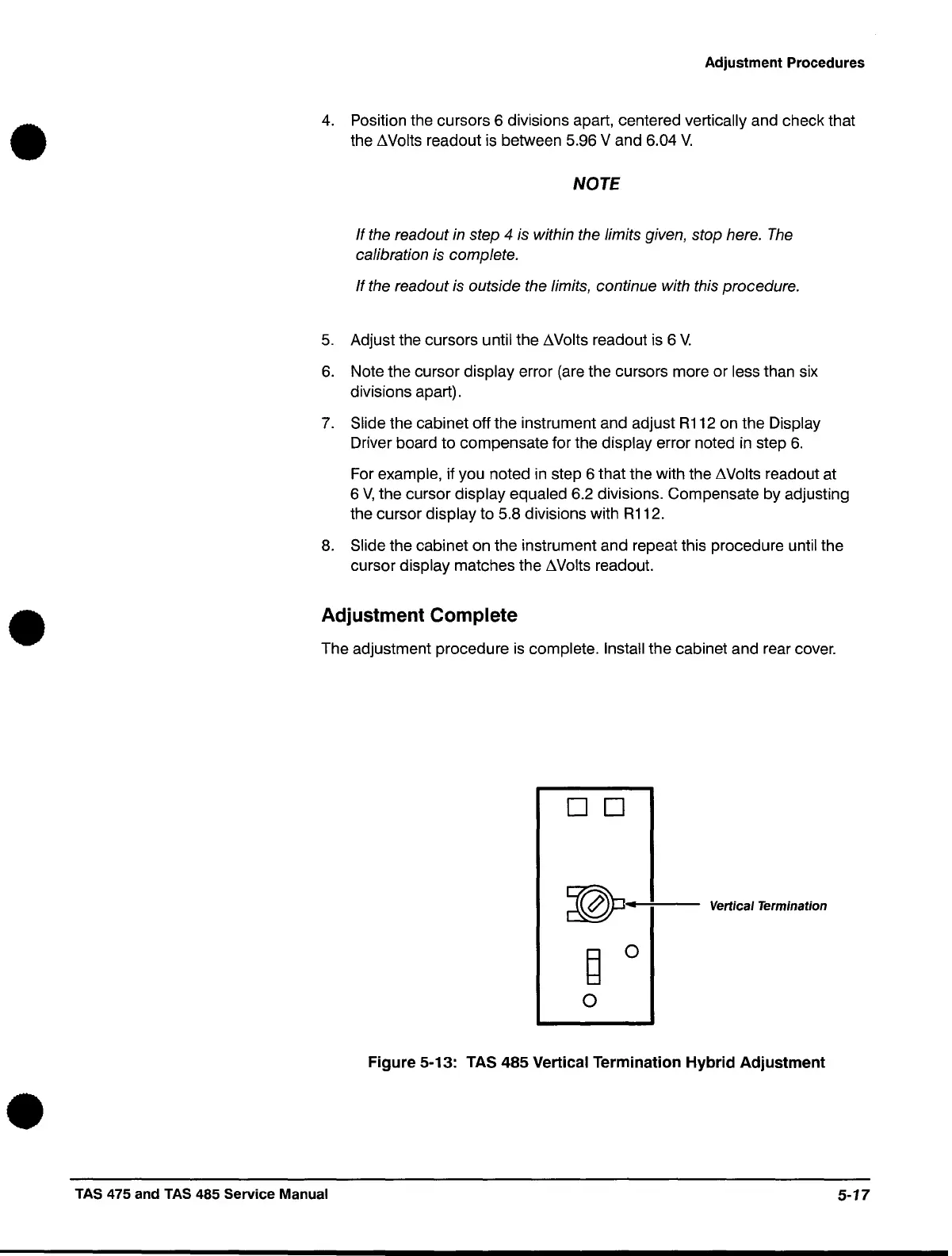
Vertical Termination
Figure 5-13: TAS
485
Vertical Termination Hybrid Adjustment
5-17
 Loading...


