•
•
•
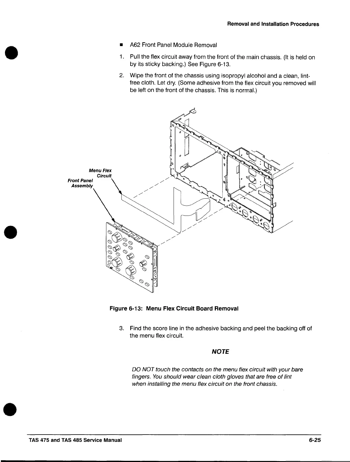
Menu Flex
Circuit
Front Panel
Assembly
Removal and Installation Procedures
• A62 Front Panel Module Removal
1.
Pull the flex circuit away from the front of the main chassis.
(It
is
held on
by its sticky backing.) See Figure 6-13.
2.
Wipe the front of the chassis using isopropyl alcohol and a clean, lint-
free cloth. Let dry. (Some adhesive from the flex circuit you removed will
be left on the front of the chassis. This
is
normal.)
./
./
./
./
./
./
./
./
./
./
./
./
./
./
./
./
./
./
./
Figure 6-13: Menu Flex
Circuit
Board Removal
3.
Find the score line
in
the adhesive backing and peel the backing off of
the menu
flex circuit.
TAS 475 and
TAS
485 Service Manual
NOTE
DO NOT touch the contacts on the menu flex circuit with your bare
fingers.
You
should wear clean cloth gloves that are free
of
lint
when installing the menu flex circuit on the front chassis .
6-25
 Loading...


