•
•
•
Performance Tests
21. Press the TRIGGER MENU button and set MODE to Trig
After
.
22. Press the SET LEVEL TO 50% button and confirm a stable delayed
sweep display.
23. Set
SLOPE
to
Falling.
24. Press the SET LEVEL TO 50% button and confirm a stable delayed
sweep display.
25. Press the HORIZONTAL MENU button and set DELAY to Off.
High
Frequency - The following steps check trigger sensitivity at
150
MHz
(TAS
475) or
250
MHz
(TAS
485).
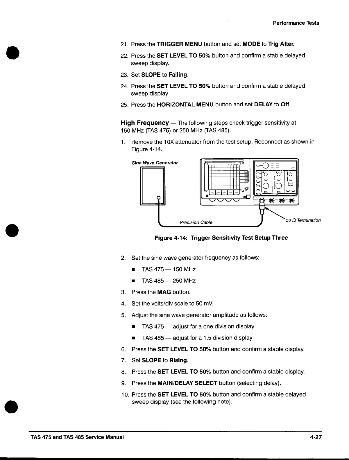
1.
Remove the 1
OX
attenuator from the test setup. Reconnect as shown
in
Figure 4-14.
Sine Wave
Generator
o
o
o
o
@
.00000
:r
'-../
'-../ '-../
'-../
=-0
00
00
0
~'O
'0'
10
• 0
10
to
·0
10
El
0
0
00
...,.0
l~
Precision Cable J '" 50 Q Termination
'--------------------'
Figure
4-14: Trigger
Sensitivity
Test Setup Three
2.
Set the sine wave generator frequency
as
follows:
•
TAS
475
-150
MHz
•
TAS
485
- 250 MHz
3.
Press the MAG button.
4.
Set the volts/div scale to
50
mV.
5.
Adjust the sine wave generator amplitude as follows:
•
TAS
475 - adjust for a one division display
•
TAS
485
- adjust for a 1.5 division display
6.
Press the SET LEVEL TO 50% button and confirm a stable display.
7.
Set SLOPE to Rising.
8.
Press the SET LEVEL TO 50% button and confirm a stable display.
9.
Press the MAIN/DELAY SELECT button (selecting delay).
10. Press the SET LEVEL TO 50% button and confirm a stable delayed
sweep display (see the following note) .
TAS 475 and TAS 485 Service Manual
4-27
 Loading...


