Diagrams and Circuit Board Illustrations
LOCATING COMPONENTS ON THE
i'RCUIT
BOARD OR SCHEMATIC DIAGRAM
9-4
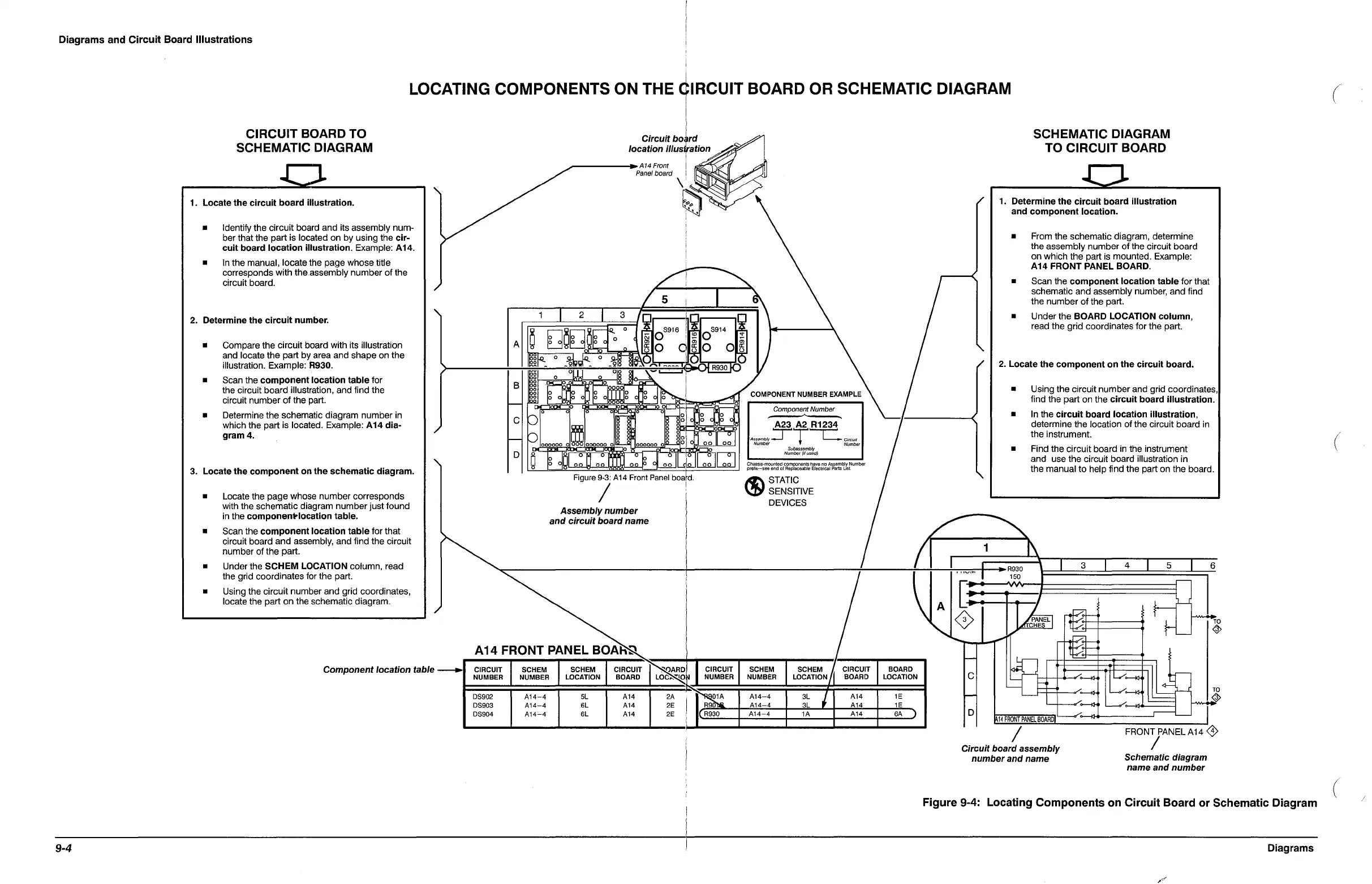
CIRCUIT BOARD TO
SCHEMATIC DIAGRAM
1.
Locate
the
circuit
board
illustration.
• Identify the circuit board and its assembly
num-
ber that the part is located
on
by using the
cir-
cuit
board
location
illustration.
Example: A14.
• In the manual, locate the page whose title
corresponds with the.assembly
number
of
the
circuit board.
2.
Determine
the
circuit
number.
• Compare the circuit board with its illustration
and locate the part by area and shape
on
the
illustration. Example: R930.
•
Scan the
component
location
table
for
the circuit board illustration, and find the
circuit
number
of
the part.
• Determine
the
schematic diagram
number
in
which the part is located. Example:
A14
dia-
gram
4.
3.
Locate
the
component
on
the
schematic
diagram.
• Locate the page whose
number
corresponds
with the schematic diagram
number
just
found
in the
component-location
table.
• Scan the
component
location
table
for
that
circuit board
and
assembly, and find the circuit
number
of the part.
• Under the
SCHEM
LOCATION column, read
the grid coordinates for the part.
• Using the circuit
number
and
grid coordinates,
locate the part
on
the schematic diagram.
Component location table
-
Circuit
bo~rd
location iIIUstation
._------.A14
Front
I
Panel
board
\'
~~
i
i
i
I
i
/1
/5
1 I 2 I 3
Ir'
.-
....
~
D~Dl
flo
a
J~
OS916
~
OS914
~J
o 0 0 0
~C\I
!T'""
,....
A a a a n.!J 0
C.!
0 0 5
oj-Q.
a %
CQ.
a
~
~
an
If'"
';1;
V
~
_
_Q1iI~
_
_Q~
I~\-"
~___
~)
g a
0.1.
a
00
~~
B
i
19
aO~
oOlg
ott
jg
og
r~
I
I--
°n
g
d g
oI~
i
g g
~
8 80
0"
000000
012-
~
0 0
00 00
~
0 ( 0 0 r
C
~
m 0
I--
i--J
000000
0
'ddd
000000
0 l
D
o
Ig
010
o~
D
o~
LTIl
00
~
J
o~
II
cio
o~
c:J
Figure 9-3: A14 Front Panel board.
/ '
Assembly
number
\
and
circuit
board
name
COMPONENT NUMBER EXAMPLE
Compone~t
Number
A23
A2
R1234
A,,,mblyTT'--C.
Ci~wl
Number
Number
Subassembly
Number
(if
used)
Cha.sslS-rnounted
components
have
no
Assembly Number
prolix-see
end of Replaceable Electncal
Parts
Us!.
R;\
STATIC
\3)1
SENSITIVE
DEVICES
A14 FRONT PANEL
BOAR~
CIRCUIT SCHEM SCHEM
CIRCUIT
~
CIRCUIT SCHEM SCHEM
CIRCUIT
NUMBER NUMBER
LOCATION
BOARD
LOC"~'O~
NUMBER
NUMBER
LOCATION
BOARD
DS902
A14-4
5L A14
2A
I
~
A14-4
3L
I
A14
DS903
A14-4
6L A14
2E
R9
A14 4
3L
A14
DS904
A14-4
6L A14 2E
R930
A14-4
lA
A14
I
BOARD
LOCATION
1E
1E
6A
")
I-
C
I-
D
SCHEMATIC DIAGRAM
TO
CIRCUIT BOARD
1.
Determine
the
circuit
board
illustration
and
component
location.
• From the schematic diagram, determine
the
assembly
number
of
the circuit board
on
which the part is mounted. Example:
A14
FRONT
PANEL BOARD.
•
Scan the
component
location
table
for
that
schematic and assembly number,
and
find
the
number
of
the part.
•
Under
the
BOARD
LOCATION
column,
read the grid coordinates for the part.
/
2.
Locate
the
component
on
the
circuit
board.
• Using the circuit
number
and grid coordinates,
find the part on the
circuit
board
illustration.
• In the
circuit
board
location
illustration,
determine
the
location
of
the circuit board in
the instrument.
• Find the circuit board in the instrument
and
use the circuit board illustration in
the manual
to
help find
the
part on the board.
1
3
4 I
5
6
L.--
~:~~~f-=:~=:.~:::~
II
~:
I~
TO
/~
--/
~
~~
~~rnrn~WWIL-~/~~--------~
1A14
FRONT
PANEL
BOARD
/
FRONT PANELA14
<3>
Circuit board assembly
number
and
name
/
Schematic diagram
name
and
number
Figure 9-4: Locating Components on Circuit Board
or
Schematic Diagram
Diagrams
(
(
(
 Loading...


