Performance Tests
II
4-28
NOTE
A slight adjustment
of
the delay time may be necessary to obtain a
stable delayed sweep display. Press the
Horizontal
Menu
button
and
adjust the delay time using the General Purpose Knob. Press
the Trigger
Menu
button after confirming a stable display.
11.
Set SLOPE to Rising.
12. Press the SET LEVEL
TO 50% button and confirm a stable delayed
sweep display.
NOTE
A slight adjustment
of
the delay time may be necessary to obtain a
stable delayed sweep display. Press the
Horizontal
Menu
button
and adjust the delay time using the General Purpose Knob.
13.
Press the HORIZONTAL MENU button and set DELAY to Off.
14.
Disconnect the test setup from the oscilloscope.
Video Trigger - The following steps check the video trigger sensitivity.
Equipment Required:
One NTSC Television signal generator (item 13), one
750
termination (item 4), and one
75
0 coaxial cable (item 6).
1.
Display channel
1,
turning
all
others
off.
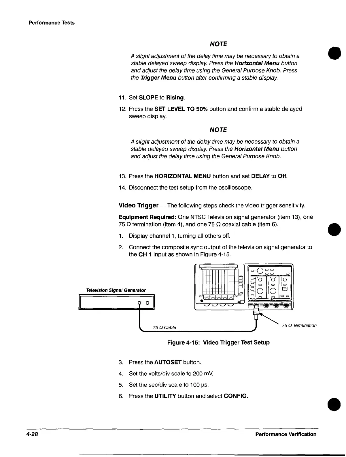
2.
Connect the composite sync output of the television signal generator to
the CH 1 input as shown in Figure 4-15.
o
o
o
o
=-ODD
DO
0
Television Signal Generator
011
~.~-r;.~o~'"f'O~,:-r.I'--O
. 0
10
to
. 0
10
E3
I~m~@
0
DO
~C)
0 0
C) C)
:r
'h.....
Cl
C)
'-"
'-" '-" '-"
~'b(j)
=
~=(j)
~
75QTe=;nat;M
'----------------------------'
75 n Cable
Figure 4-15: Video Trigger Test Setup
3.
Press the AUTOSET button.
4.
Set the volts/div scale to 200
mV.
5.
Set the sec/div scale to 100
\.ls.
6.
Press the UTILITY button and select CONFIG.
Performance Verification
•
•
•
 Loading...


