Removal and Installation Procedures
7.
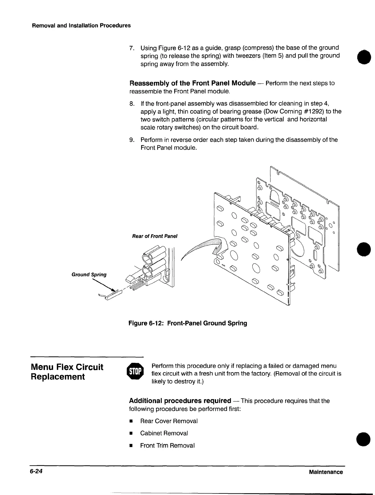
Using Figure 6-12
as
a guide, grasp (compress) the base of the ground
spring (to
release the spring) with tweezers (Item
5)
and pull the ground
.-
spring away from the assembly.
Menu Flex Circuit
Replacement
6-24
Reassembly
of
the
Front Panel Module - Perform the next steps to
reassemble the Front Panel module.
8.
If
the front-panel assembly was disassembled for cleaning in step
4,
apply a light, thin coating of bearing grease (Dow Corning #1292) to the
two switch patterns (circular patterns for the vertical and horizontal
scale rotary switches) on the circuit board.
9.
Perform
in
reverse order each step taken during the disassembly of the
Front
Panel
module.
Figure 6-12: Front-Panel Ground
Spring
Perform this procedure only if replacing a failed or damaged menu
flex circuit with a fresh unit from the factory. (Removal of the circuit is
likely to destroy it.)
Additional procedures required - This procedure requires that the
following procedures be performed first:
•
Rear
Cover Removal
• Cabinet Removal
• Front
Trim
Removal
Maintenance
•
•
 Loading...


