•
•
•
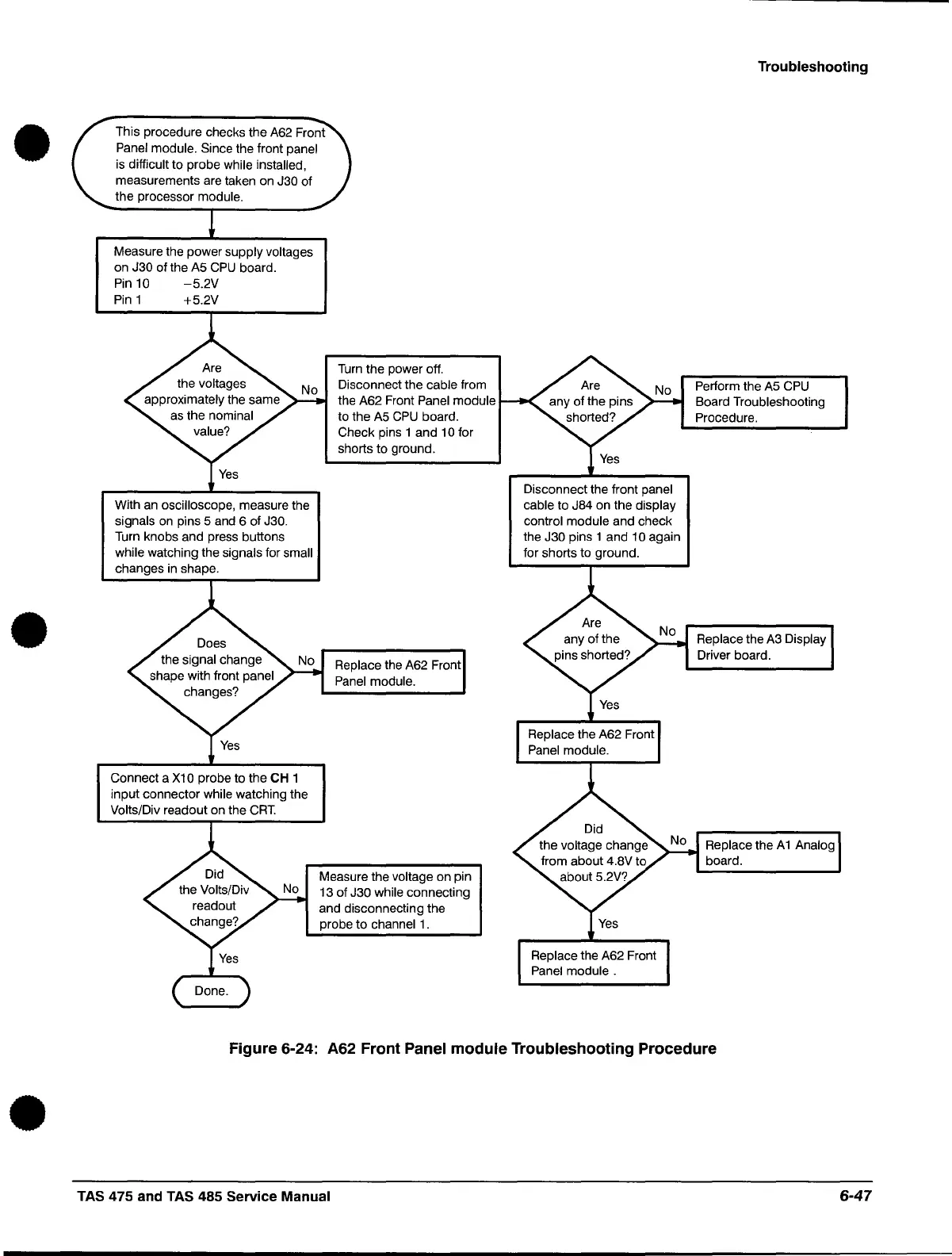
This procedure checks the A62 Front
Panel module. Since the front panel
is
difficult to probe while installed,
measurements are taken on J30 of
the processor
module.
Measure the power supply voltages
on J30 of the A5
CPU
board.
Pin
10
-5.2V
Pin
1 +5.2V
With
an
oscilloscope, measure the
signals
on
pins 5 and 6 of J30.
Turn knobs and press buttons
while watching the
signals for small
changes in shape .
Connect a
X1
0 probe to the CH 1
input connector
while watching the
Volts/Div readout on the
CRT.
Turn the power off.
Disconnect the
cable from
the A62 Front
Panel module
to the A5
CPU
board.
Check pins 1 and
10
for
shorts to ground.
Replace the A62 Front
Panel module.
Measure the voltage on pin
13 of
J30 while connecting
and disconnecting the
probe
to
channel
1.
Disconnect the front panel
cable
to J84 on the display
control module
and check
the
J30 pins 1 and 10 again
for shorts to ground.
Troubleshooting
Perform the A5
CPU
Board Troubleshooting
Procedure.
Replace
the A3 Display
Driver board.
Replace the A 1 Analog
board.
Figure 6-24: A62 Front Panel module Troubleshooting Procedure
TAS 475 and TAS 485 Service Manual
6-47
 Loading...


