•
•
•
Horizontal System
Checks
Performance Tests
9.
Disconnect the test setup from the oscilloscope.
10.
Repeat this procedure until all input channels are verified.
Check X-Axis Gain
Equipment Required: One pulse generator (item
10)
and one precision
coaxial cable (item
5).
1.
Display channel
1,
turning all others off.
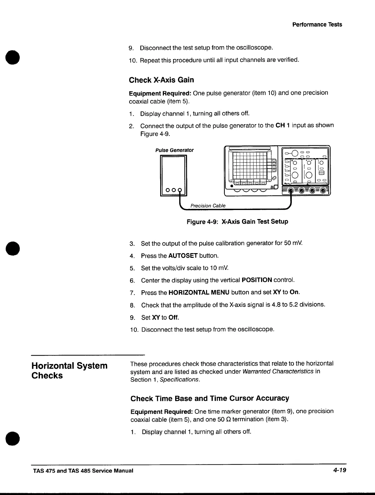
2.
Connect the output of the pulse generator to the CH 1 input
as
shown
Figure 4-9.
p
ulse Generator
I
I
o--Q
a a
a a
a
a
ij'
'0'
fO
a
. 0
a
. a
fa
[a
a
·0
lo
E3
@
a
a a
a a a
a a
... _ a
a
•
OO(
.:r
'-"
'-"
'-" '-"
§"~
~-=(j)=(j)=(j),
Precision Cable
~
Figure 4-9: X-Axis Gain Test Setup
3.
Set the output of the pulse calibration generator for
50
mV.
4.
Press the AUTOSET button.
5.
Set the volts/div scale to 10
mV.
6.
Center the display using the vertical POSITION control.
7.
Press the HORIZONTAL MENU button and set
XV
to On.
8.
Check that the amplitude of the
X-axis
signal is 4.8 to 5.2 divisions.
9.
Set
XV
to Off.
10.
Disconnect the test setup from the oscilloscope.
These procedures check those characteristics that relate to the horizontal
system and are listed
as
checked under Warranted Characteristics
in
Section
1,
Specifications.
Check Time Base and Time Cursor Accuracy
Equipment Required: One time marker generator (item
9),
one precision
coaxial cable (item
5),
and one
50
Q termination (item
3).
1.
Display channel
1,
turning
all
others off.
TAS 475 and TAS 485 Service Manual
4-19
 Loading...


