•
•
•
Compensating the
Probe
Quick Start
!
I
.....
...,.......-t.,.·
....
'"
.t---t--r.,..
....
.
...
1O--+-+---+---+---+-+--+--+----t--lJ---+-----'
CLEAR
MENU
~~J~;!;;;;;~~~~~~~l~
....................
@
lollo
0 0
oj
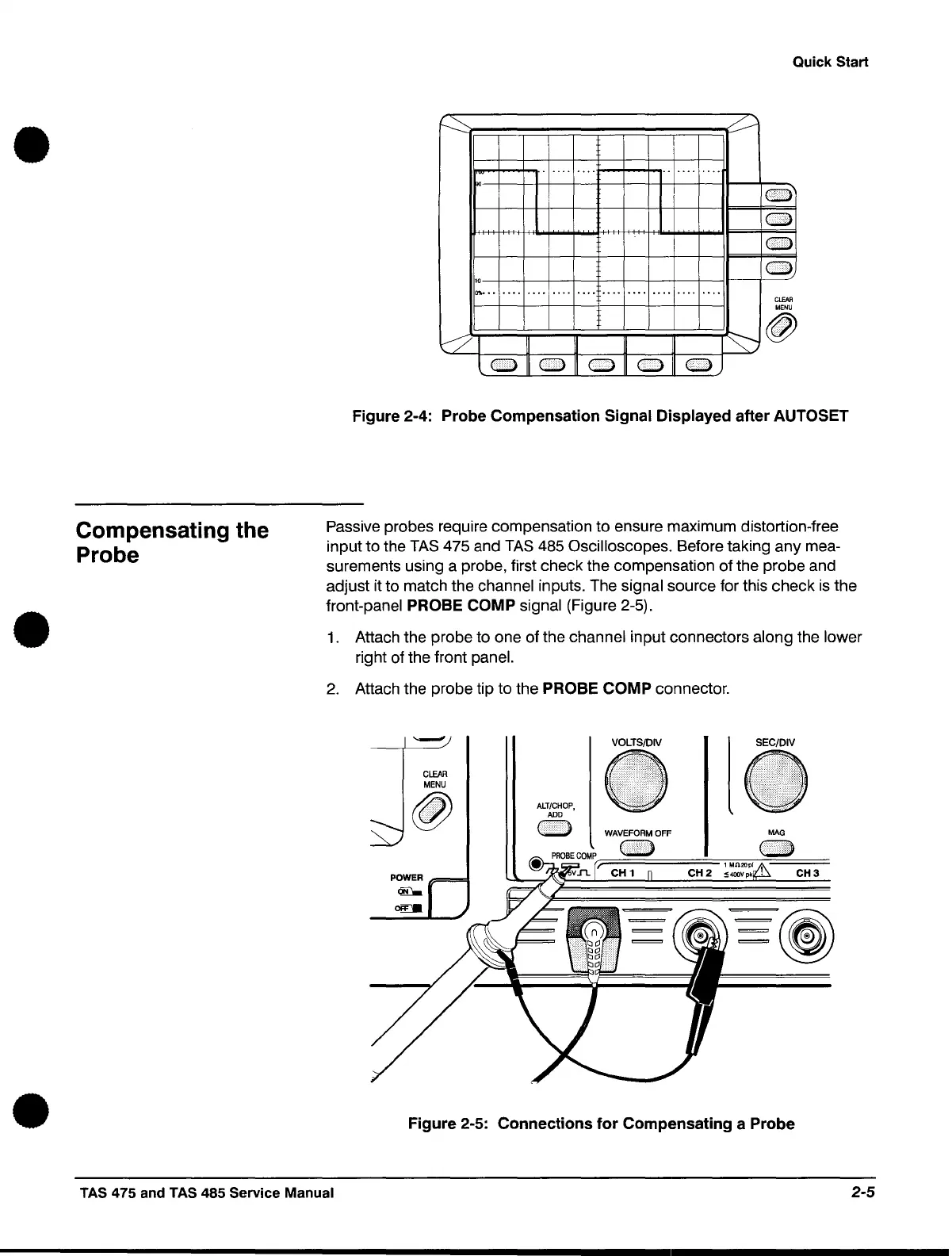
Figure 2-4: Probe Compensation Signal Displayed after AUTOSET
Passive probes require compensation to ensure maximum distortion-free
input to the
TAS
475 and
TAS
485 Oscilloscopes. Before taking any mea-
surements using a probe, first check the compensation of the probe and
adjust it to match the channel inputs. The signal source for this check
is
the
front-panel
PROBE COMP signal (Figure 2-5).
1.
Attach the probe to one of the channel input connectors along the lower
right of the front panel.
2.
Attach the probe tip to the PROBE COMP connector.
CLEAR
MENU
@
POWER
~
0ffI
ALT/CHOP,
ADD
o
VOLTS/DIV
~
l
SEC/DIV
~
MAG
Figure 2-5: Connections for Compensating a Probe
TAS 475 and TAS 485 Service Manual
2-5
 Loading...


