Adjustment Procedures
5-12
t----~
/-----,
100
••
.... .... .... .
...
.... ....
.
...
.
...
....
90
a
Lines Six Divisions
a
Apart,
Centered
a
Vertically
a
10
0%.'
•
....
....
....
.
...
....
.
...
.... .... ....
ClEAR
MENU
VLJ
l~-"'"
@
La
0 a 0
0)
Figure 5-10: Adjusting Vertical Gain and Centering
15.
Select Done when you have completed the adjustments.
16.
Select Done again to exit the routine.
High Frequency Step Response
Equipment Required: One pulse generator (item 10), one precision coaxial
cable
(item
5),
one
2X
attenuator (item
1),
and one
50
Q termination (item
3).
Adjustment Locations: This procedure requires adjustments to the Display
Driver board and the Vertical Termination hybrid. See Figures 5-14 and 5-15
on pages 5-18 and 5-19 for the
location of the Display Driver board adjust-
ments.
See Figure 5-13 on page 5-17 for the location of the Vertical
Termination hybrid adjustment.
Prerequisites: Factory
Vertical
Cal
adjustment procedure.
1.
Display channel
1,
turning all others off.
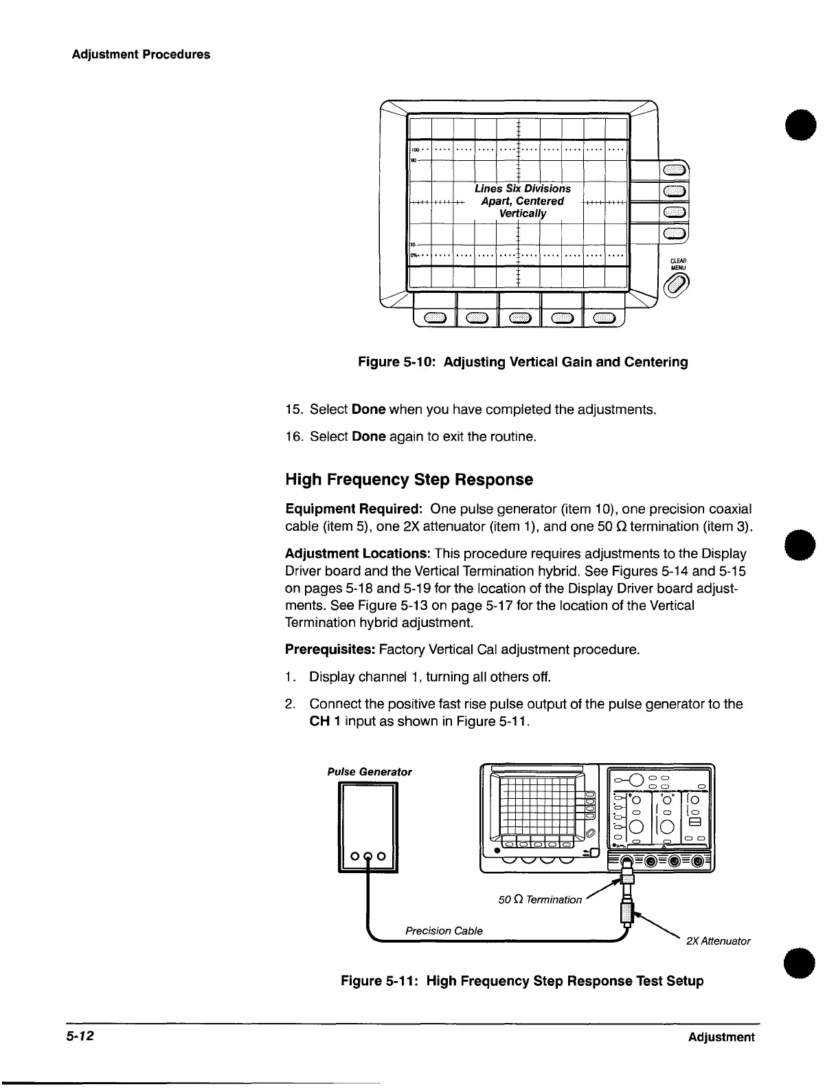
2.
Connect the positive fast rise pulse output of the pulse generator to the
CH 1 input
as
shown
in
Figure 5-11.
p
ulse
Generator
=-0
a a
a a
"ii.
a
~.
'0'
rO
a
. 0
a
. a
ro
lo
a
·0
10
E3
@
a
a a
a a a a a
....,.0
a
0
0
•
.:r
'-"
'-" '-"
'-"
EI
fiiI
=(j)=(j)=(j)~
/q
500
Te~;n'"M
~~
Precision Cable
) 2XAtte
nuator
Figure 5-11: High Frequency Step Response Test Setup
Adjustment
•
•
•
 Loading...


