•
•
•
Installation
Power On
Before you begin using the
TAS
475 and
TAS
485 Analog Oscilloscopes,
ensure proper installation.
Perform this procedure to
properly install and power on the
TAS
475 and
TAS
485 Analog Oscilloscopes.
1.
Check that you have the proper electrical connections. The
TAS
475 and
TAS
485 Analog Oscilloscopes require 90 to 132
VACRMS
or 180 to
250
VACRMS,
continuous range for 48 Hz to 440
Hz.
A maximum of
85 Watts may be required.
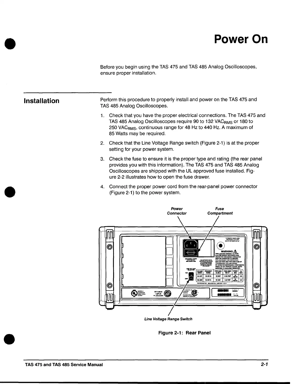
2.
Check that the Line Voltage Range switch (Figure 2-1) is at the proper
setting for your power system.
3.
Check the fuse to ensure it
is
the proper type and rating (the rear panel
provides you with this information). The
TAS
475 and
TAS
485 Analog
Oscilloscopes
are shipped with the UL approved fuse installed. Fig-
ure 2-2
illustrates how to open the fuse drawer.
4.
Connect the proper power cord from the rear-panel power connector
(Figure 2-1) to the power system.
Power
Connector
Line Voltage Range Switch
Fuse
Compartment
I
.-.~.
I
---
.~~':;
Figure 2-1: Rear Panel
TAS 475 and TAS 485 Service Manual
2-1
 Loading...


