Removal and Installation Procedures
A63 Power Supply
Module
6-34
• Front
Trim
Removal
•
A3
Display Driver Board
•
CRT
1.
Unplug the cables from connectors J80, J82, and J84 on the
A2
Display
Control
board.
2.
Lift the
A2
Display Control board up toward the top of the chassis,
sliding the board out of the board retainers.
3.
Re-install the
A2
Display Control board by sliding the board into the
board retainers.
4.
Re-install all cables at connectors J80, J82, and J84.
5.
Install
all
previously removed components.
The procedures that follow describe how to remove and install the Power
Supply module.
Additional procedures required - This procedure requires that the
following procedures be performed first:
• Rear Cover Removal
•
Cabinet Removal
Power
Supply
Removal
1.
Set the oscilloscope so its top down on the work surface.
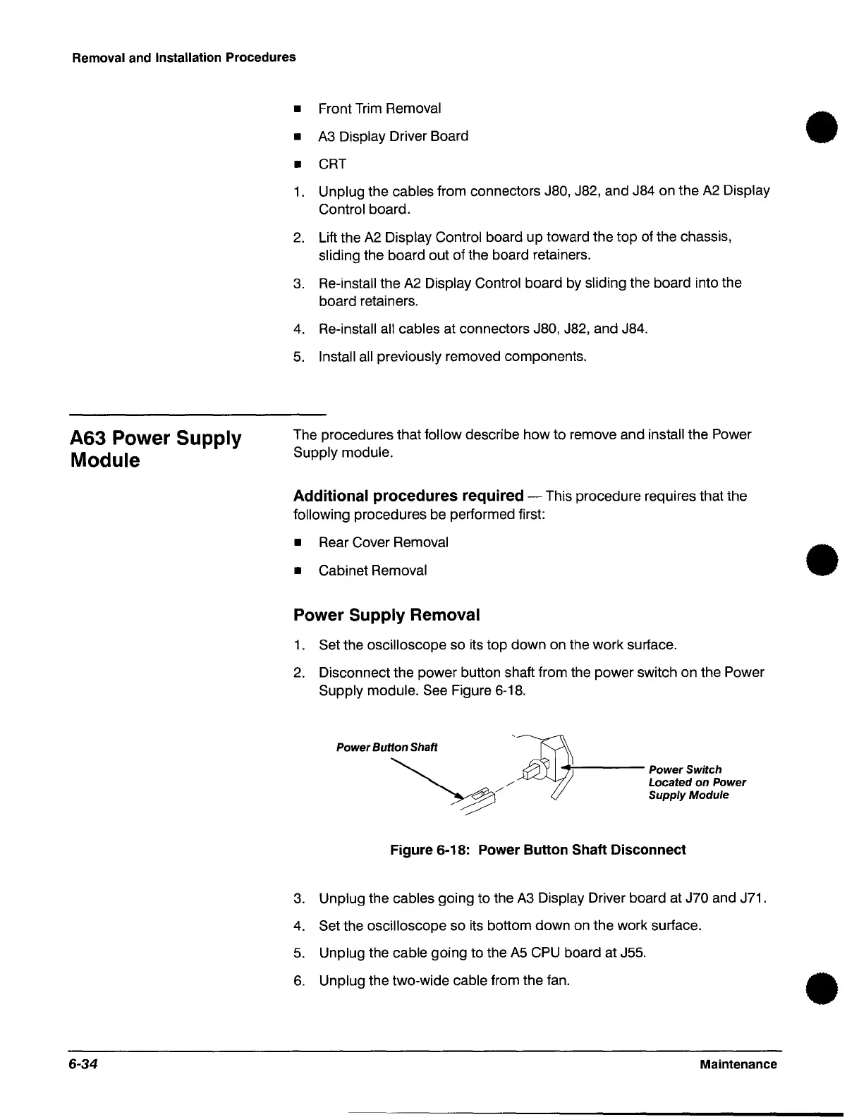
2.
Disconnect the power button shaft from the power switch on the Power
Supply module.
See
Figure
6-18.
Power Button Shaft
././
A.V'~I
--'
Located on Power
~
+-----
Power
Switch
Supply Module
Figure 6-18: Power
Button
Shaft Disconnect
3.
Unplug the cables going to the
A3
Display Driver board at J70 and J71.
4.
Set the oscilloscope so its bottom down on the work surface.
5.
Unplug the cable going to the
A5
CPU
board at J55.
6.
Unplug the two-wide cable from the fan.
Maintenance
•
•
•
 Loading...


