Removal and Installation Procedures
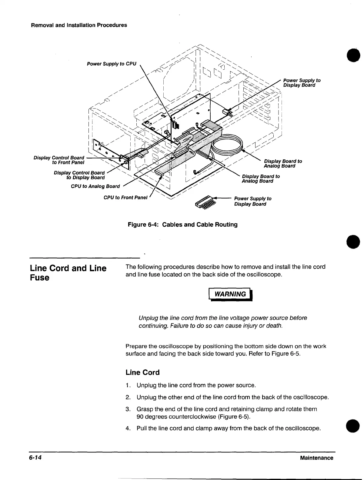
Power Supply to CPU
/'
r<-',
/"/
1
<-"
""
"
1
I""
"
1 !
1 i
II
1 : •
~
/'
/'
/'
/'
/'
/'
Power Supply to
Display Control Board
-...::'-~::::...,,~~!SI~""
Display Board to
Analog Board
to Front Panel
Display Control Board
to Display Board
CPU
to Analog Board
Display Board
to
Analog Board
CPU
to Front Panel
~
Power Supply to
Line Cord and Line
Fuse
6-14
~
Display Board
Figure 6-4:
Cables
and Cable Routing
The
following procedures describe how to remove and install the line cord
and
line fuse located on the back side of the oscilloscope.
WARNING I
Unplug the line
cord
from the line voltage
power
source before
continuing. Failure to do so can cause injury
or
death.
Prepare the oscilloscope by positioning the bottom side down on the work
surface and facing the back side toward you. Refer
to
Figure 6-5.
Line Cord
1.
Unplug the line cord from the power source.
2.
Unplug the other end of the line cord from the back of the oscilloscope.
3.
Grasp the end of the line cord and retaining clamp and rotate them
90 degrees counterclockwise (Figure 6-5).
4.
Pull the line cord and clamp away from the back of the oscilloscope.
Maintenance
•
•
•
 Loading...


