Adjustment Procedures
5-6
6.
Press the VERTICAL MENU button and set CPLG to AC.
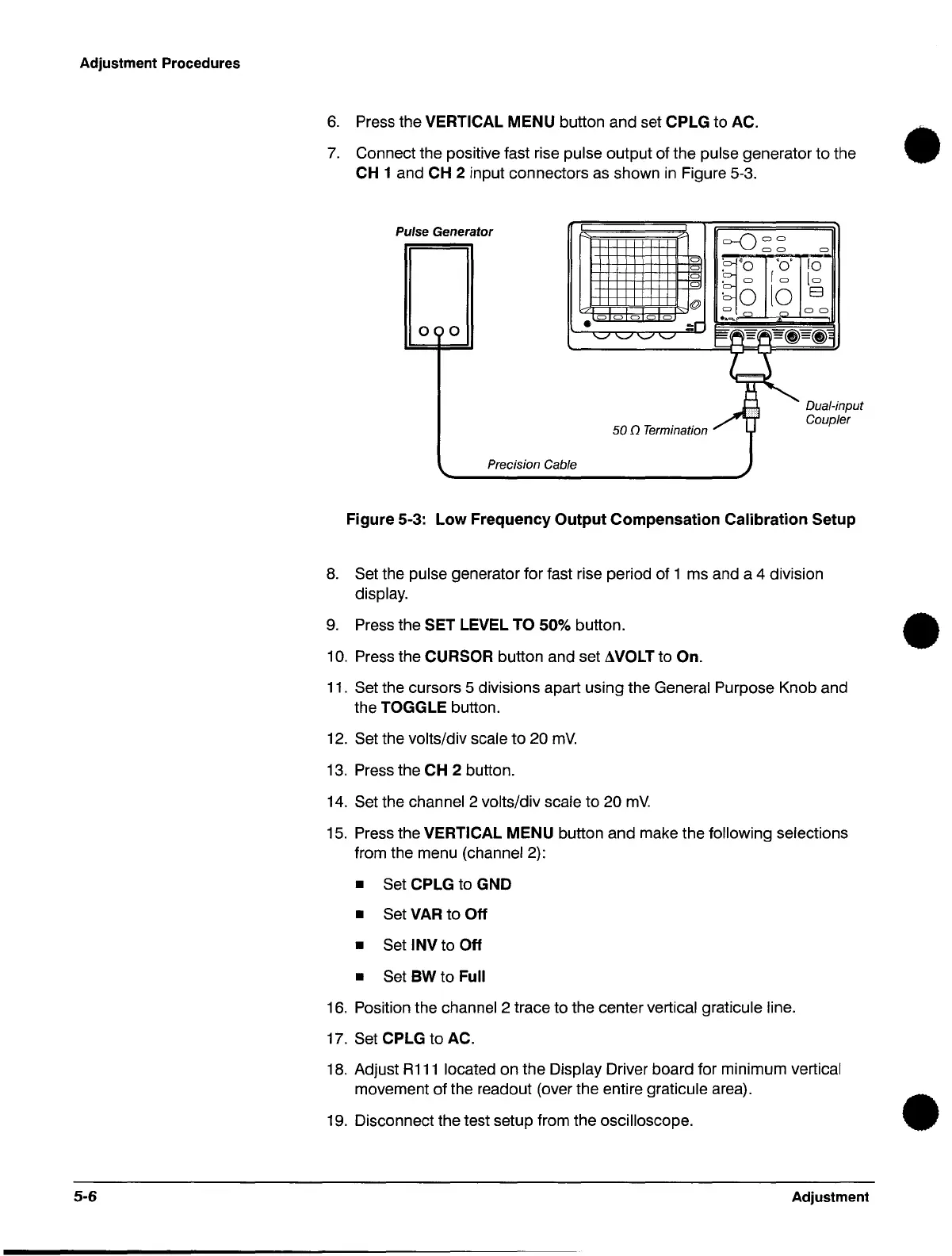
7.
Connect the positive fast rise pulse output of the pulse generator to the
CH 1 and CH 2 input connectors as shown
in
Figure 5-3.
p
ulse Generator
I
I
C)
0
0
0
@
0 o 0 o 0
:r
O(
0
•
'-"
'-"
'-"
'-"
50 n Termination
Precision Cable
0-()
00
00
0
~'O
'0'
[0-
• 0
[0
lo
10
E3
·0
o
_0
"
o 0
..
..,
E~'d"~~~=~~
~
1 Dua/-i
~
Coupl
nput
er
Figure 5-3:
Low
Frequency
Output
Compensation Calibration Setup
8.
Set the pulse generator for fast rise period of 1 ms and a 4 division
display.
9.
Press the SET LEVEL TO 50% button.
10.
Press the CURSOR button and set AVOLT to On.
11.
Set the cursors 5 divisions apart using the General Purpose Knob and
the TOGGLE button.
12.
Set the volts/div scale
to
20
mY.
13.
Press the CH 2 button.
14.
Set the channel 2 volts/div scale to 20
mY.
15.
Press the VERTICAL MENU button and make the following selections
from the menu (channel 2):
• Set CPLG to GND
• Set VAR to
Off
• Set INV to Off
• Set
BW to Full
16.
Position the channel 2 trace to the center vertical graticule line.
17. Set CPLG
to
AC.
18.
Adjust
R111
located on the Display Driver board for minimum vertical
movement of the readout (over the entire graticule area).
19.
Disconnect the test setup from the oscilloscope.
Adjustment
•
•
•
 Loading...


