Performance
Tests
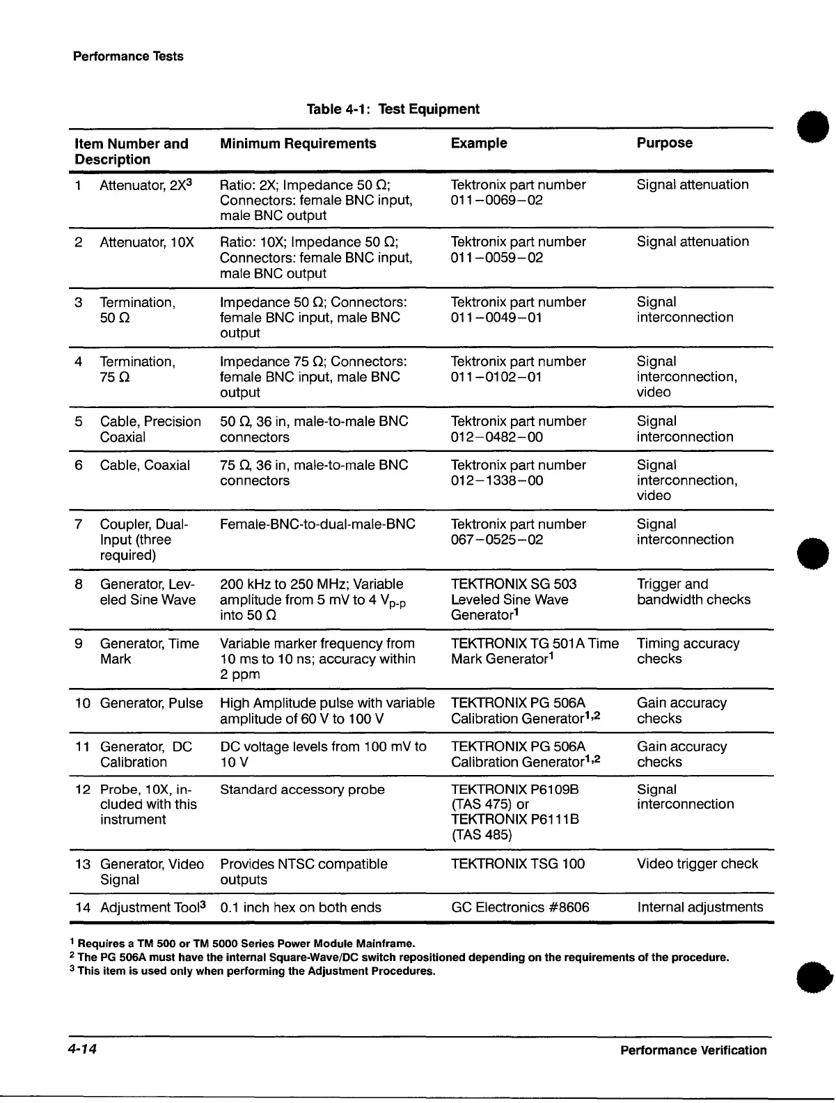
Table 4-1: Test
Equipment
•
Item
Number
and
Minimum
Requirements
Example
Purpose
Description
1 Attenuator,
2X3
Ratio:
2X;
Impedance 50
0;
Tektronix part number Signal attenuation
Connectors: female BNC input,
011-0069-02
male BNC output
2 Attenuator, 10X
Ratio:
10X;
Impedance 50
0;
Tektronix part number Signal attenuation
Connectors: female BNC input,
011-0059-02
male BNC output
3
Termination,
Impedance 50
0;
Connectors:
Tektronix part number
Signal
500
female BNC input, male BNC
011-0049-01
interconnection
output
4 Termination,
Impedance 75
0;
Connectors:
Tektronix part number
Signal
750
female BNC input, male BNC
011
-0102-01
interconnection,
output
video
5
Cable,
Precision 50
n,
36 in, male-to-male BNC
Tektronix part number
Signal
Coaxial connectors
012-0482-00
interconnection
6
Cable, Coaxial 75
n,
36
in,
male-to-male BNC Tektronix part number
Signal
connectors
012-1338-00
interconnection,
video
7 Coupler, Dual- Female-BNC-to-dual-male-BNC Tektronix part number
Signal
Input (three 067 - 0525 - 02
interconnection
•
required)
8
Generator, Lev-
200 kHz to 250 MHz; Variable TEKTRONIX
SG
503 Trigger and
eled
Sine Wave amplitude from 5 mV to 4 V
p
_
p
Leveled Sine Wave
bandwidth checks
into
50 0 Generator
1
9 Generator, Time Variable marker frequency from TEKTRONIX
TG
501
A Time
Timing accuracy
Mark 10 ms to 10 ns; accuracy within Mark Generator
1
checks
2 ppm
10
Generator,
Pulse High Amplitude pulse with variable
TEKTRONIX
PG
506A Gain accuracy
amplitude of
60 V to 100 V
Calibration Generator
1
,2
checks
11
Generator, DC
DC
voltage levels from 100 mV to TEKTRONIX
PG
506A Gain accuracy
Calibration 10 V
Calibration Generator
1
,2
checks
12
Probe, 10X, in- Standard accessory probe
TEKTRONIX P6109B Signal
cluded with this
(TAS
475) or
interconnection
instrument
TEKTRONIX
P6111
B
(TAS
485)
13 Generator, Video
Provides NTSC compatible TEKTRONIX TSG 100
Video trigger check
Signal outputs
14 Adjustment
Tool3
0.1
inch hex on both ends GC Electronics #8606
Internal adjustments
1 Requires a TM 500
or
TM 5000 Series Power
Module
Mainframe.
2 The
PG
506A
must
have the internal Square-Wave/DC
switch
repositioned
depending
on
the
requirements
of
the
procedure.
•
3 This item
is
used
only
when performing
the
Adjustment Procedures.
4-14
Performance Verification
 Loading...


