Adjustment Procedures
5-14
NOTE
The
position
of
the leads from the Vertical Termination hybrid to the
CRT affect the high frequency step response. Unless the leads
have been repositioned, it may
not
be
necessary to adjust them.
Some interaction
of
the adjustments made in steps e through i may
occur. For optimum oscilloscope performance, these steps should
be
rechecked after making adjustments.
7.
Disconnect the calibration setup from the oscilloscope.
Attenuator Compensation
Equipment Required: One pulse generator (item 10), one precision coaxial
cable
(item
5),
one
50
Q termination (item
3),
and three dual-input couplers
(item
7).
Adjustment Locations: This procedure requires adjustments to the Analog
board. See Figure 5-16 on page 5-20 for the location of the adjustments.
Prerequisites: Low Frequency Output Compensation adjustment proce-
dure.
1.
Display channel
1,
turning all others
off.
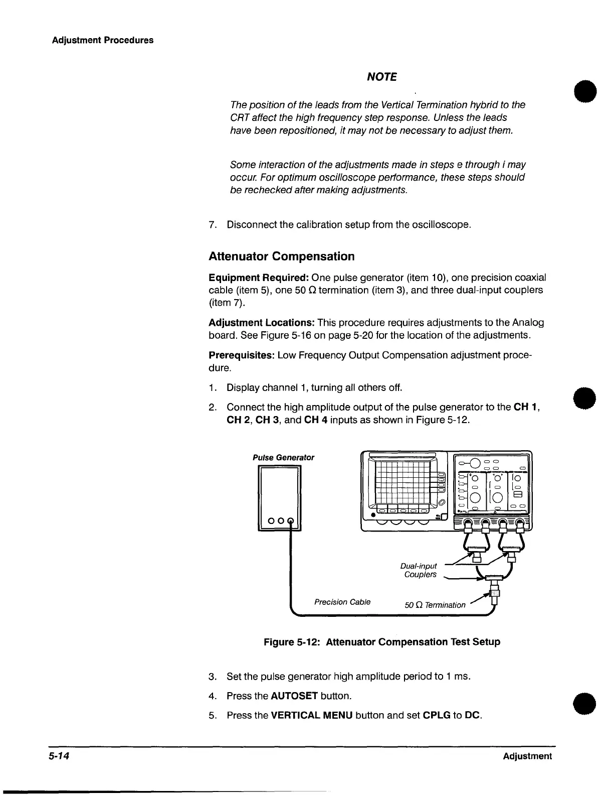
2.
Connect the high amplitude output of the pulse generator to the CH
1,
CH 2, CH
3,
and CH 4 inputs
as
shown
in
Figure 5-12.
Pulse Generator
=-0
C)
C)
C) C)
C)
•
00
Precision Cable
C) C)
C)
Dual-input
Couplers
C)
C)
C)
C)
@
~'O
•
C)
·0
C)
..
...,.
50 0 Termination
'0'
IC)
to
Figure 5-12: Attenuator Compensation Test Setup
3.
Set the pulse generator high amplitude period to 1 ms.
4.
Press the AUTOSET button.
5.
Press the VERTICAL MENU button and set CPLG to DC.
C)
10
[C)
E3
C) C)
Adjustment
•
•
•
 Loading...


