•
•
•
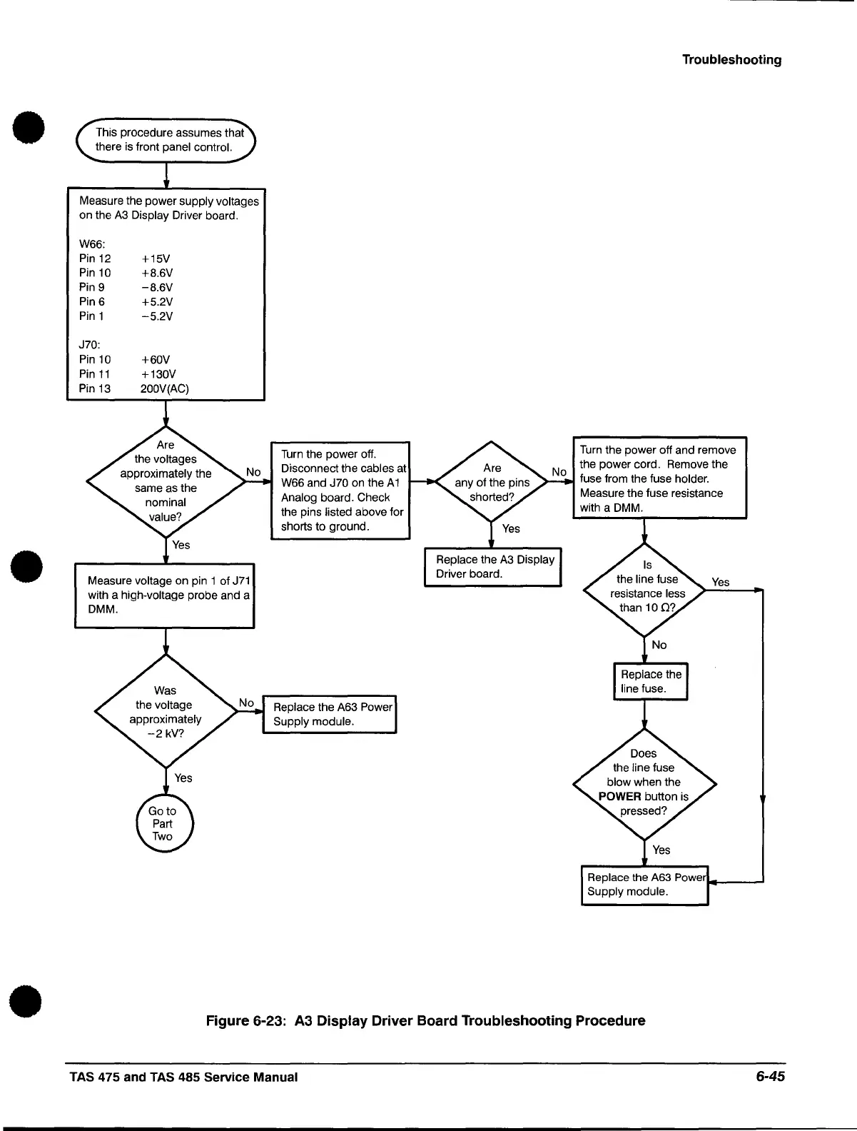
This procedure assumes that
there is front
panel control.
Measure the power supply voltages
on the
A3
Display Driver board.
W66:
Pin 12
+1SV
Pin 10
+B.6V
Pin 9
-B.6V
Pin6
+S.2V
Pin 1
-S.2V
J70:
Pin 10
+60V
Pin
11
+130V
Pin 13 200V(AC)
Measure voltage on pin 1 of
J71
with a high-voltage probe and a
DMM.
Turn
the power off.
Disconnect the
cables at
W66 and
J70 on the A 1
Analog board. Check
the pins
listed above for
shorts to ground .
Replace the A63 Power
Supply module
.
Troubleshooting
Turn the power off and remove
the power cord. Remove the
fuse from the fuse
holder.
Measure the fuse resistance
with a DMM.
Figure 6-23:
A3
Display Driver Board Troubleshooting Procedure
TAS 475 and TAS 485 Service Manual
6-45
 Loading...


