•
•
•
Trigger System
Checks
Performance Tests
26.
Press the UTILITY button and select Dual Delay Disabled.
27. Press the HORIZONTAL MENU button and set DELAY
to
Off
28.
Disconnect the test setup from the oscilloscope.
These procedures check those characteristics that relate
to
the trigger
system and are
listed as checked under Warranted Characteristics
in
Section
1,
Specifications.
Check Trigger Sensitivity
Equipment Required: One sine wave generator (item 8), one 10X attenuator
(item 2), one preCision
coaxial cable (item 5), one dual-input coupler
(item 7), and one 50 Q termination (item 3).
Low
Frequency
- The following steps check trigger sensitivity at 25 MHz.
1.
Display channel 1 , turning all others off.
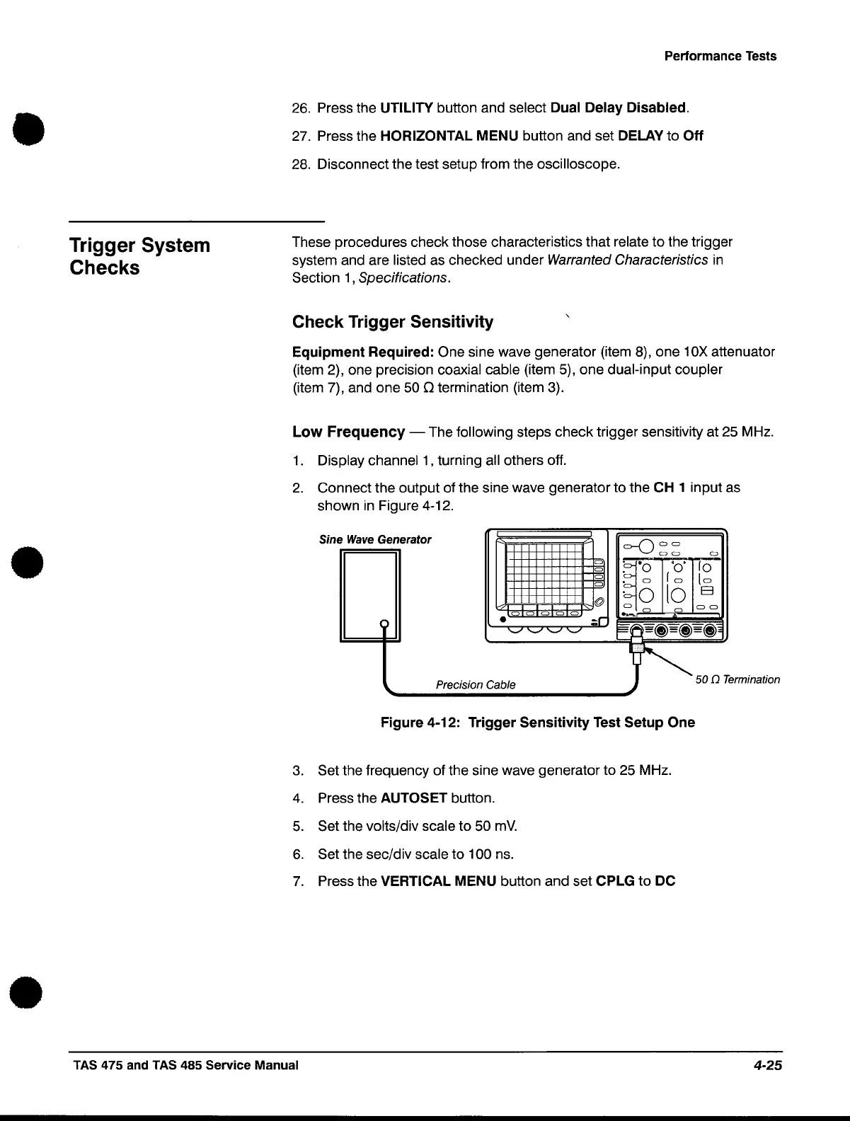
2.
Connect the output of the sine wave generator to the CH 1 input as
shown
in
Figure 4-12.
Sine
Wave
Generator
C)
C)
C)
C)
Figure 4-12: Trigger Sensitivity
Test
Setup One
3.
Set the frequency of the sine wave generator to 25 MHz.
4.
Press the AUTOSET button.
5.
Set the volts/div scale to 50
mY.
6.
Set the sec/div scale to 100 ns.
7.
Press the VERTICAL MENU button and set CPLG
to
DC
TAS 475 and TAS 485 Service Manual
4-25
 Loading...


