)
)
)
1
Pin Number
Sequence Path
?)
Highe"
Pin
/~
Number Index
13
12
11
10
26
25
24
23
39 38
37
36
44
43
-
f--
49 48
~
'--
54
53
60
59
58
~
~
70 69
-
r---
75 74
88
87 86
85
101 100
99
98
114
113
112
111
6
Pin Number
/~
Highest Pin 1
Number Index
9
8
7 6 5 4 3 2
1
22
21
20
19
18
17
16 15 14
35
34
33
32
31
30
29 28
27
41
42
40
47
46
45
52
51
50
57
56 55
63
62
61
68
67
66
73 72
71
84 83 82
81
80
79 78 77 76
97
96
95 94 93
92
91
90
89
110
109 108 107 106 105
104
103 102
13 12
11
10
9 8 7 6 5 4 3 2
A
B
C
o
E
F
G
H
J
K
L
M
N
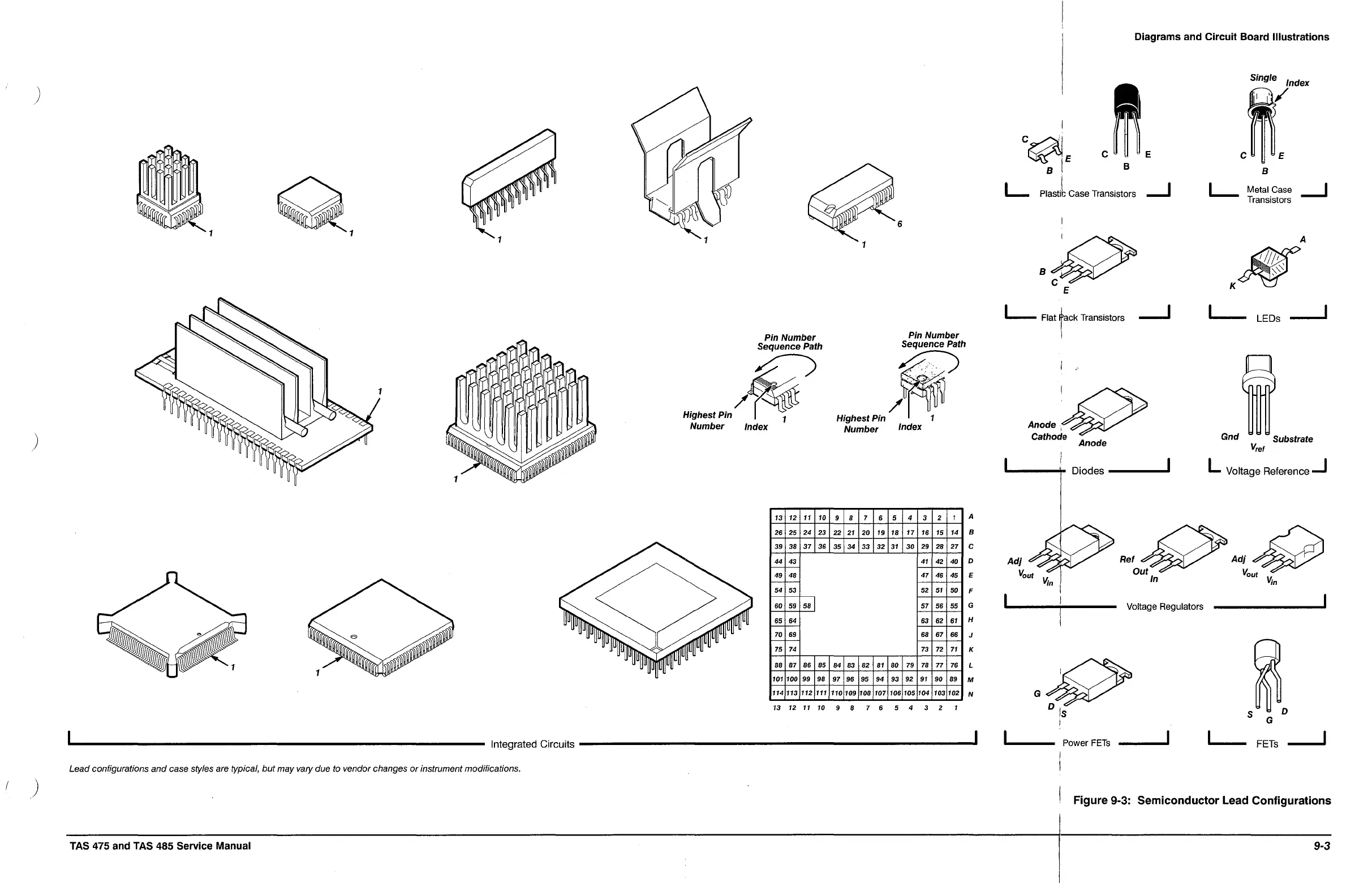
Integrated Circuits
-------------------------------
.....
Lead configurations
and
case styles are typical,
but
may val}' due to vendor changes
or
instrument modifications.
TAS 475 and TAS 485 Service Manual
Diagrams and Circuit Board Illustrations
I
C~I
~E
C
B
L
Plastt
Case Transistors
.~
E
L-
Flat
tack
Transistors
E
An~e~
Cathode Anode
Diodes
----
...
C E
B
L-
Metal Case
---1
Transistors
LEDs
Gnd Substrate
Vref
L Voltage Reference
...J
Ref~AdiM
Out V
out
In
V;n
Voltage Regulators
G~
D
Is
Power
FETs
I
I
S
G
FETs
Figure 9-3: Semiconductor Lead Configurations
9-3
 Loading...


