•
•
•
Removal and Installation Procedures
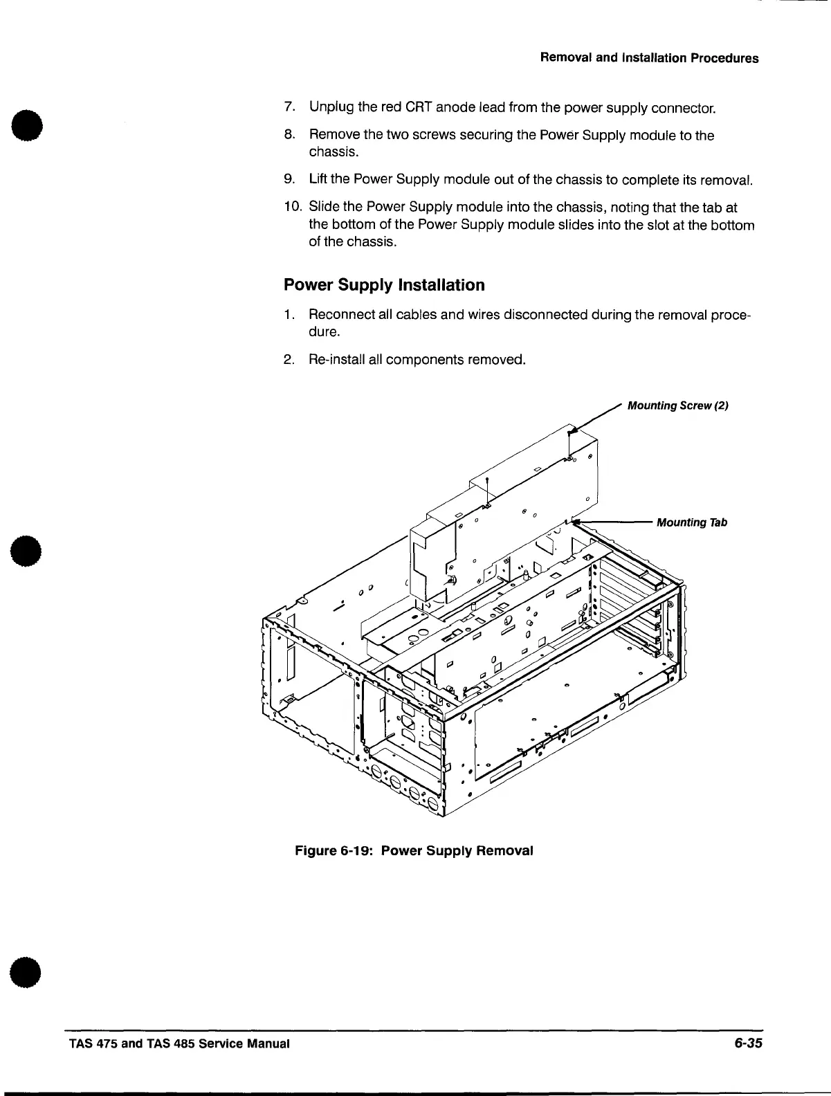
7.
Unplug the red
CRT
anode lead from the power supply connector.
8.
Remove the two screws securing the Power Supply module to the
chassis.
9.
Lift the Power Supply module out of the chassis to complete its removal.
10.
Slide the Power Supply module into the chassis, noting that the tab at
the bottom of the Power
Supply module slides into the slot at the bottom
of the chassis.
Power Supply Installation
1.
Reconnect all cables and wires disconnected during the removal proce-
dure.
2.
Re-install
all
components removed.
Mounting
Screw (2)
A.,...----
Mounting
Tab
Figure
6-19:
Power
Supply
Removal
TAS
475 and
TAS
485 Service Manual
6-35
 Loading...


