•
•
•
Performance Tests '
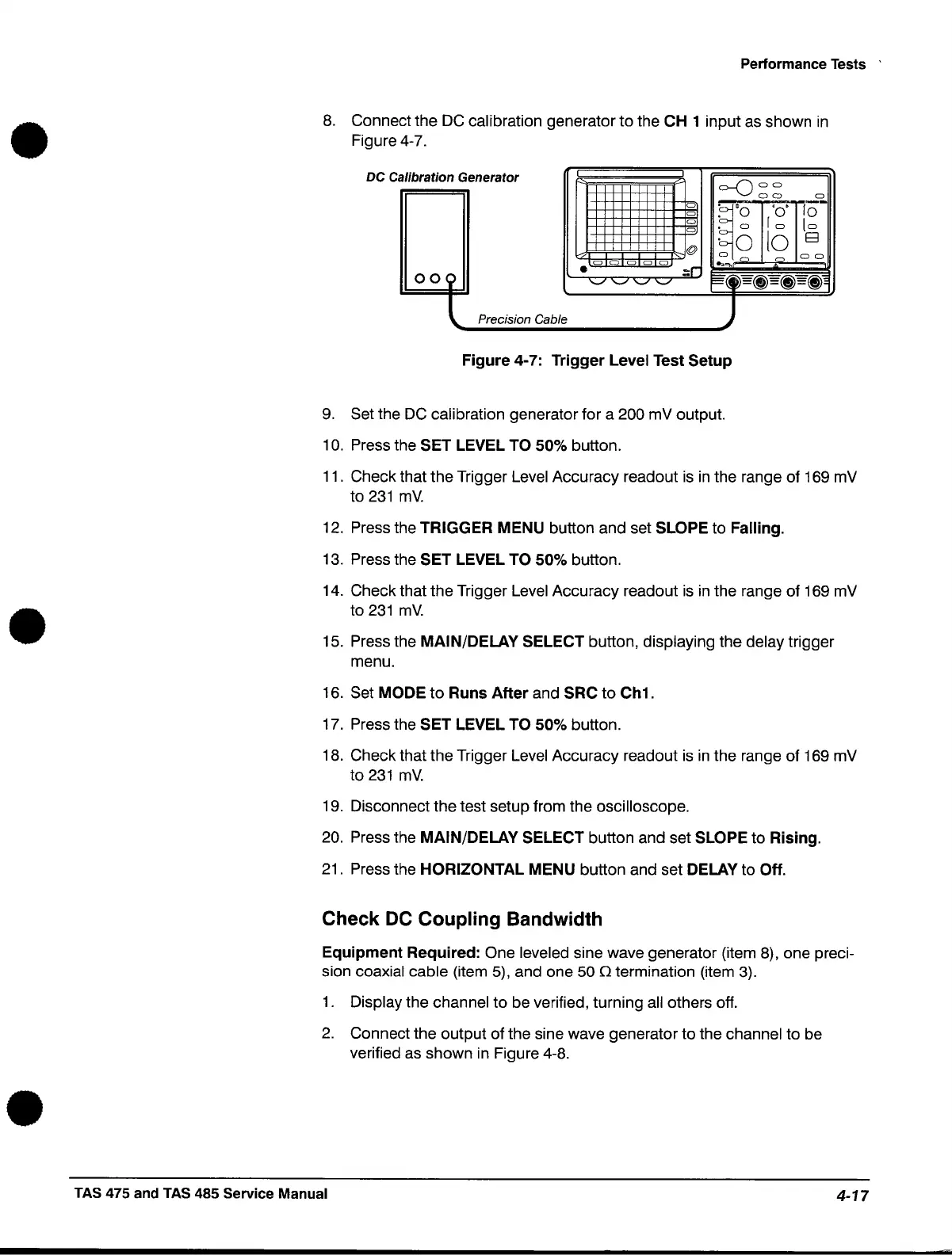
8.
Connect the
DC
calibration generator to the CH 1 input
as
shown
in
Figure 4-7.
Dee
alibration Generator
I
I
=-0 a a
a a a
a
~'O
'0'
lO-
a
a
. a
10
[a
a
10
E3
'0
@
o~
a
a a
C)
a a
CJ
a
:r
...
.,.
009
•
'-' '-'
'-'
'-'
~~
~b(j)=(j)=(j)
,
Precision Cable
Figure 4-7: Trigger Level Test Setup
9. Set the
DC
calibration generator for a 200 mV output.
10.
Press the SET LEVEL TO 50% button.
11.
Check that the Trigger Level Accuracy readout
is
in
the range of 169 mV
to
231
mV.
12.
Press the TRIGGER MENU button and set SLOPE to Falling.
13.
Press the SET LEVEL TO 50% button.
14.
Check that the Trigger Level Accuracy readout
is
in
the range of 169 mV
to
231
mV.
15. Press the MAIN/DELAY SELECT button, displaying the delay trigger
menu.
16. Set
MODE
to
Runs
After
and SRC to Ch1.
17. Press the SET LEVEL TO 50% button.
18. Check that the Trigger Level Accuracy readout
is
in
the range of 169 mV
to
231
mY.
19. Disconnect the test setup from the oscilloscope.
20. Press the MAIN/DELAY SELECT button and set SLOPE to Rising.
21. Press the
HORIZONTAL MENU button and set DELAY to Off.
Check
DC
Coupling Bandwidth
Equipment Required: One leveled sine wave generator (item 8), one preci-
sion coaxial cable (item 5), and one 50
(}
termination (item 3).
1.
Display the channel
to
be verified, turning
all
others off.
2.
Connect the output of the sine wave generator to the channel to be
verified as shown
in
Figure 4-8 .
TAS 475 and TAS 485 Service Manual
4-17
 Loading...


