•
•
•
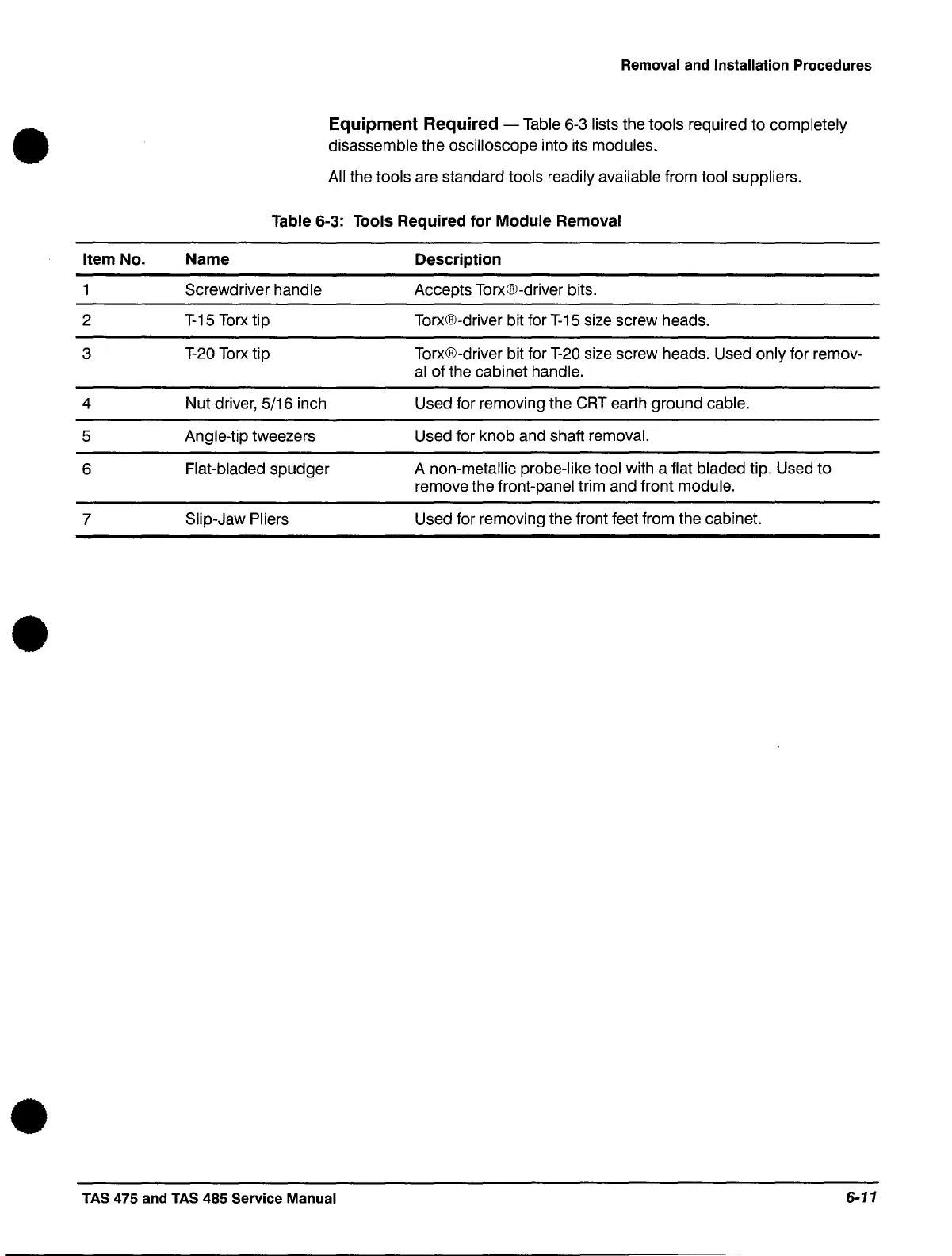
Item No.
2
3
4
5
6
7
Removal and Installation Procedures
Equipment Required - Table 6-3 lists the tools required
to
completely
disassemble
the
oscilloscope into its modules.
All
the tools are standard tools readily available from tool suppliers.
Table 6-3: Tools Required
for
Module
Removal
Name
Screwdriver handle
T-15
Torx
tip
T-20
Torx tip
Nut
driver, 5/16 inch
Angle-tip tweezers
Flat-bladed
spudger
Slip-Jaw Pliers
Description
Accepts Torx®-driver bits.
Torx®-driver bit for
T-15
size screw heads.
Torx®-driver bit for
T-20
size screw heads. Used
only
for remov-
al
of
the cabinet handle.
Used for removing the CRT earth
ground
cable.
Used for
knob
and shaft removal.
A non-metallic probe-like tool with a flat bladed tip. Used
to
remove the front-panel trim and front module.
Used for removing the front feet from the cabinet.
TAS 475 and
TAS
485 Service Manual
6-11
 Loading...


