Quick Start
2-6
3.
Select the appropriate input channel by pressing either the CH
1,
CH
2,
CH
3,
or CH 4 front-panel button. •
4.
With the probe attached between
an
input channel and the probe com-
pensation output of the oscilloscope, press the
AUTOSET button on the
front
panel.
5.
Set the vertical scale to 1 V using the VOLTS/DIV control.
6.
Center the waveform vertically using the vertical POSITION control.
7.
Set the horizontal scale to 200
J.ls
using the SEC/DIV control.
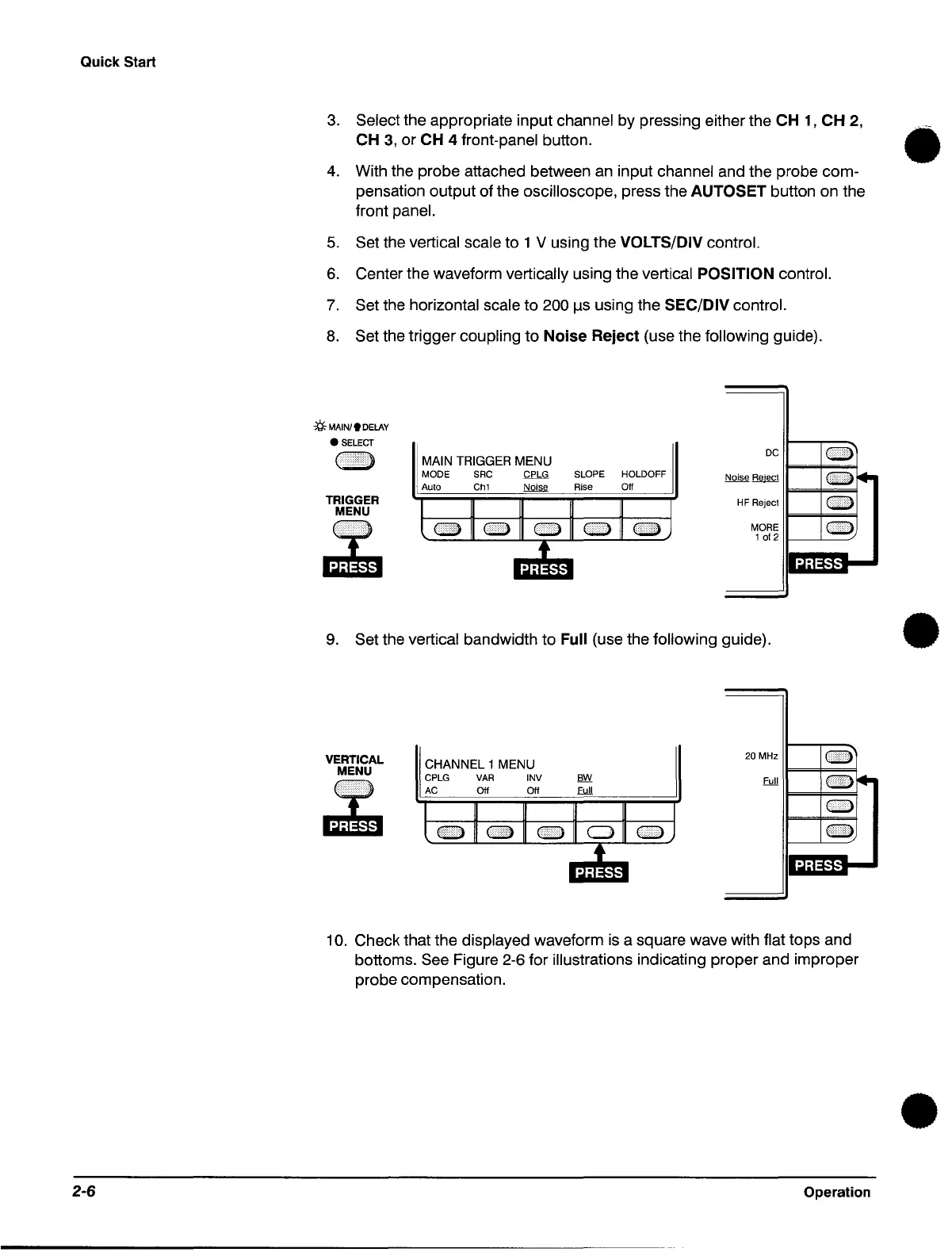
8.
Set the trigger coupling to
Noise
Reject
(use the following guide).
:tf::
MAIN/I
DELAY
•
SELECT
TRIGGER
MENU
~
MAIN TRIGGER MENU
MODE SRC CPLG
Auto
Ch1
~
SLOPE HOLDOFF
Rise Off
DC
H F Reject
c:::::>
MORE
c:::::>
1
of
2
11-----'----'
DoI~
9.
Set the vertical bandwidth to Full (use the following guide).
VERTICAL
MENU
~
CHANNEL 1 MENU
20 MHz
CPLG
VAR
INV
AC
Off Off
10.
Check that the displayed waveform
is
a square wave with flat tops and
bottoms.
See Figure 2-6 for illustrations indicating proper and improper
probe compensation.
Operation
•
•
 Loading...


