Groundsmaster 4300--D Hydraulic SystemPage 4 -- 69
NOTE: Traction pump and gear pump should be re-
moved from machine as an assembly. Once removed
from machine, pumps can be separated for service.
Removal (Fig. 67)
1. Parkthemachineonalevelsurface,engageparking
brake, lower cutting decks and stop engine. Remove
key from the ignition switch.
2. Read the General Precautions for R emoving and
Installing Hydraulic System Components at the begin-
ning of the Service and Repairs section of this chapter.
CAUTION
Beforeopeninghydraulicsystem,operateallhy-
draulic controls to relieve system pressure and
avoid injury from pressurized hydraulic oil. See
RelievingHydraulicSystemPressurein theGen-
eral Information section of this chapter.
3. To prevent contamination of the hydraulic system,
thoroughly cleantraction and gear pumpassembly and
all hydraulic connections.
4. Labelhydraulic hosestoassistin assembly.Discon-
nect all hydraulic hoses and tubes from fittings on the
traction and gear pump assembly. Allow hydraulic lines
to drain into a suitable container. Plug or cap openings
of pumps and lines to prevent contamination.
5. Remove hydraulic pump drive shaft (see Hydraulic
Pump Drive Shaft Removal in this section).
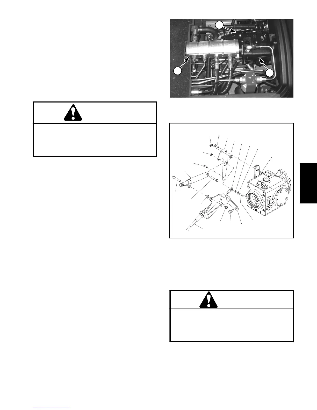
6. Separate traction cable assembly from traction
pump (Fig. 69):
A. Removeflangenut(item4inFig.69)thatsecures
lever damper (item 14 in Fig. 69) to traction cable
bracket.
B. Remove cap screws (items 7 and 13 in Fig. 69)
andlocknut(item8inFig.69)thatsecuretractionle-
ver bracket (item 12 in Fig. 69) to pump lever.
C. Loosen jam nuts that secure traction cable to
traction cable bracket (item 6 in Fig. 69).
D. Position traction cable assembly away from
pump assembly.
7. Disconnect wire harness electrical connector from
traction neutral switch and position harness away from
transmission.
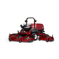
1. Piston (traction) pump
2. Gear pump
3. Traction cable bracket
Figure 68
2
1
3
1. Cap screw (2 used)
2. Flange nut (2 used)
3. Traction cable
4. Flange nut (2 used)
5. Flange screw (2 used)
6. Traction cable bracket
7. Cap screw (2 used)
8. Lock nut (2 used)
9. Flat washer
10. Flat washer
11. Ball joint
12. Traction lever bracket
13. Cap screw
14. Lever damper
Figure 69
6
5
7
3
1
2
8
4
1
2
4
7
8
9
10
12
11
13
14
CAUTION
Make sure lift or hoist can support the total
weight of the pump assembly before removing
the cap screws from the pump assembly and
frame.Pumpassembly weighs approximately 67
pounds (30.5 kg).
8. Connectaliftorhoisttoholeintractionc ablebracket
on traction pump to s upport pump assembly and for
pump removal.
Hydraulic
System

 Loading...