Groundsmaster 4300--D Hydraulic SystemPage 4 -- 37
4. Raise and support operator seat to allow access to
hydraulic pump assembly.
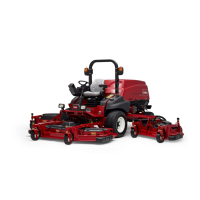
5. Thoroughly clean ends of hydraulic tubes that con-
nectto theoilfilter(Fig.37).Disconnecthydraulic tubes
from oil filter adapter. Remove two (2) flange head
screwsthatsecureoilfilteradaptertoframeandremove
oil filter and adapter assembly from machine.
6. Install tee fitting with 1000 PSI (70 bar) pressure
gaugeinplaceofthe removedhydraulic filterassembly.
7. Make sure thattraction pedal isin neutral, thesteer-
ing wheel is stationary and parking brake is engaged.
8. Startengineandrunatidlespeed.Checkforanyhy-
draulic leakage from test connections and correct be-
fore proceeding with test.
9. Place throttle to full speed (3200 RPM) and monitor
pressure gauge on tester.
GAUGEREADINGTOBEapproximately 200 to
250 PSI (13.8 to 17.2 bar)
10.Next,determinechargepressureundertractionload
byoperatingthemachineinadirectforwardandreverse
direction (not steering). Make sure that engine is run-
ning at full speed (3200 RPM). Apply the brakes and
pressthetractionpedalintheforwarddirectionandthen
to reverse while monitoring the pressure gauge. Stop
engine and record test results.
GAUGEREADINGTOBEapproximately 150 to
250 PSI (13.8 to 17.2 bar)
11.Compare measured charge pressure from step 9
with pressure from step 10:
A. Ifchargepressureisgoodundernoload(step9),
but drops below specification w hen under traction
load(step10),thepistonpumpshouldbesuspected
of wear and inefficiency. When the pump is worn or
damaged,thechargesystemis notable toreplenish
losttractioncircuitoilduetoexcessiveleakageinthe
worn pump.
B. If there isno charge pressure,or pressureis low,
checkforrestrictioningearpumpintakeline.Inspect
charge relief valve and valve seat in the traction
pump(seeTractionPumpServiceintheServiceand
Repairs section of this chapter). Also, consider a
worn or damaged gear pump ( P3) (see Gear Pump
(P3) Flow Test in this section).
NOTE: If gear pump (P3) is worn or damaged, both
charge circuit and steering circuit will be affected.
12.After charge pressure testing is completed, make
surethat engine isnot runningand then relievehydrau-
lic system pressure (See Relieving Hydraulic System
Pressure in the General Information section of this
chapter). Remove pressure gauge and tee fitting from
hydraulic tubes. Install oil filter to machine.
13.Lower and secure operator seat.
1. Hydraulic tube
2. Oil filter / filter adapter
3. Hydraulic tube
Figure 37
1
3
2
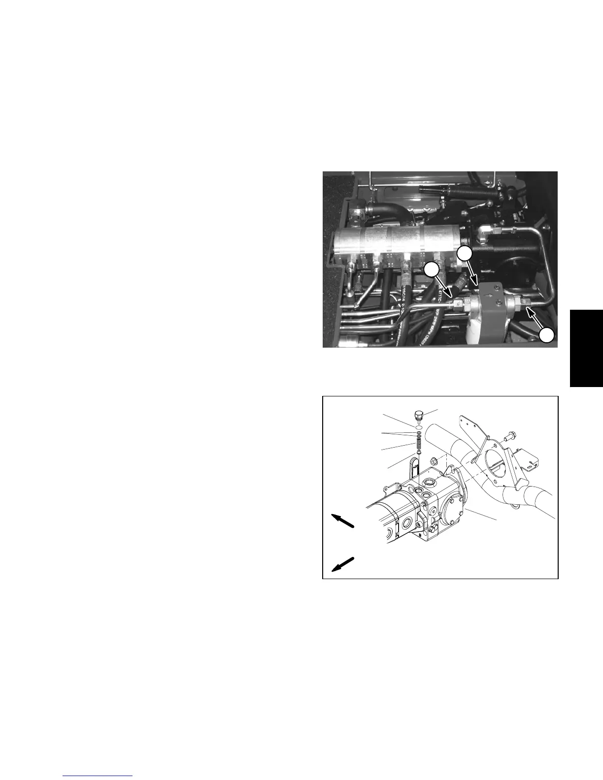
1. Traction pump
2. Plug
3. O--ring
4. Shim kit
5. Spring
6. Charge relief poppet
Figure 38
2
3
1
FRONT
RIGHT
4
5
6
Hydraulic
System

 Loading...