Groundsmaster 4300--DPage 5 -- 22Electrical System
Component Testing
For accurate resistance and/or continuity checks, elec-
tricallydisconnect thecomponentbeing testedfrom the
circuit (e.g. unplug the ignition switch connector before
doing a continuity check of the switch).
NOTE: Electrical troubleshooting of any 12 volt power
connectioncanbeperformedthroughvoltagedroptests
without disconnecting the component.
NOTE: Use the Diagnostic Display (see Special Tools
inthischapter)totestTECcontroller inputsandoutputs
before further troubleshooting of an electrical problem
on your Groundsmaster.
NOTE: For engine component testing information,see
the Kubota Workshop Manual, Diesel Engine, 05--E3B
Series at the end of Chapter 3 -- Kubota Diesel Engine.
CAUTION
Whentesting electrical componentsfor continu-
ity with a multimeter (ohms setting), make sure
that power to the circuit has been disconnected.
Ignition Switch
Theignition(key)switchhasthree positions(OFF,RUN
andSTART).The switchis mounted onthe controlc on-
sole.
Testing
1. Before disconnecting the ignition switch for testing,
the switch and its circuit wiring should be tested as a
TEC controller input with the Diagnostic Display (see
DiagnosticDisplayintheTroubleshootingsectionofthis
chapter). If the Diagnostic Display verifies that ignition
switchandcircuitwiringarefunctioningcorrectly,nofur-
ther switch testing is necessary. If, however, the Diag-
nosticD isplaydeterminesthatignitionswitchandcircuit
wiring are not functioning correctly, proceed with test
procedure.
2. Remove outsidecontrol armcover togain accessto
ignitionswitch(seeControlArmDisassemblyintheSer-
vice and Repairs section of Chapter 6 -- Chassis). Dis-
connect wire harness electrical connector from the
switch.
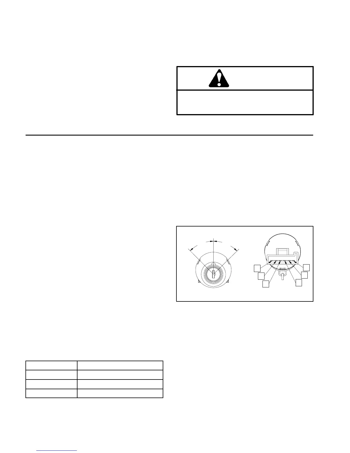
3. With the use of a multimeter (ohms setting), the
switch functions may be tested to determine whether
continuityexistsbetween thevariousterminalsforeach
switch position. The ignition switch terminals are
marked as shown in Figure 18. The c ircuitry of this
switch is shown in the chart below. Verify continuity be-
tween switch terminals.
POSITION
CIRCUIT
OFF NONE
RUN B+C+F, D+E
START A+B+C
4. Replace ignition switch if necessary.
5. If switch tests correctly and circuit problem still ex-
ists, c heck wire harness ( see Electrical Schematic and
Circuit Drawings in Chapter 8 -- Foldout Drawings).
6. Connect wire harness electrical connector to the
ignition switch.
7. Install control arm cover to machine (see Control
Arm Assembly in the Service and Repairs section of
Chapter 6 -- Chassis).
Figure 18
REAR VIEW
FRONT VIEW
A
B
C
D
E
F
START
OFF
RUN
45
o
45
o

 Loading...