Groundsmaster 4300--DHydraulic System Page 4 -- 102
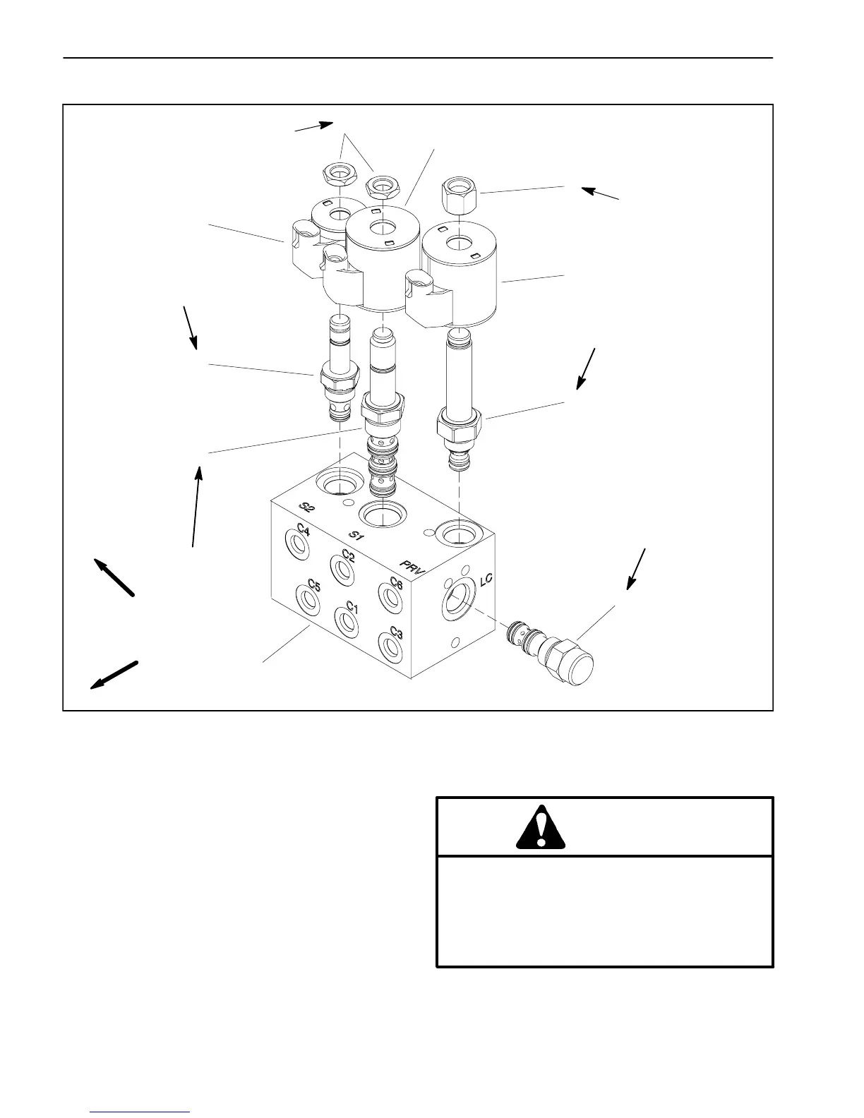
Lift Control Manifold Service
1. Lift control manifold
2. Solenoid valve (S1)
3. Solenoid valve (S2)
4. Solenoid coil
5. Nut
6. Nut
7. Solenoid coil
8. Proportional relief valve (PRV)
9. Logic cartridge (LC)
Figure 92
FRONT
RIGHT
(27 N--m)
20 ft--lb
(33 N--m)
25 ft--lb
60 in--lb
(6.7 N--m)
60 in--lb
(6.7 N--m)
(27 N--m)
20 ft--lb
(27 N--m)
20 ft--lb
2
3
6
8
9
1
5
7
4
7
NOTE: Theportsontheliftcontrolmanifoldaremarked
foreasy identificationofcomponents. Example:Pisthe
gear pump (P4) connection port and S2 is the location
forsolenoidvalveS2(seeHydraulicSchematicinChap-
ter8--FoldoutDrawingstoidentifythefunctionofthehy-
draulic lines and cartridge valves at each manifold port
location).
Forcontrolmanifoldserviceprocedures,seeDeckCon-
trol Manifold Service in this section. Refer to Figure 92
for lift control manifold cartridge valve installation
torque.
WARNING
Make sure that cutting decks are fully lowered
before loosening hydraulic lines, cartridge
valves or plugs from lift control manifold. If
decks are not fully lowered as manifold compo-
nents are loosened, decks may drop unexpect-
edly.

 Loading...