Groundsmaster 4300--D Page 5 -- 35 Electrical System
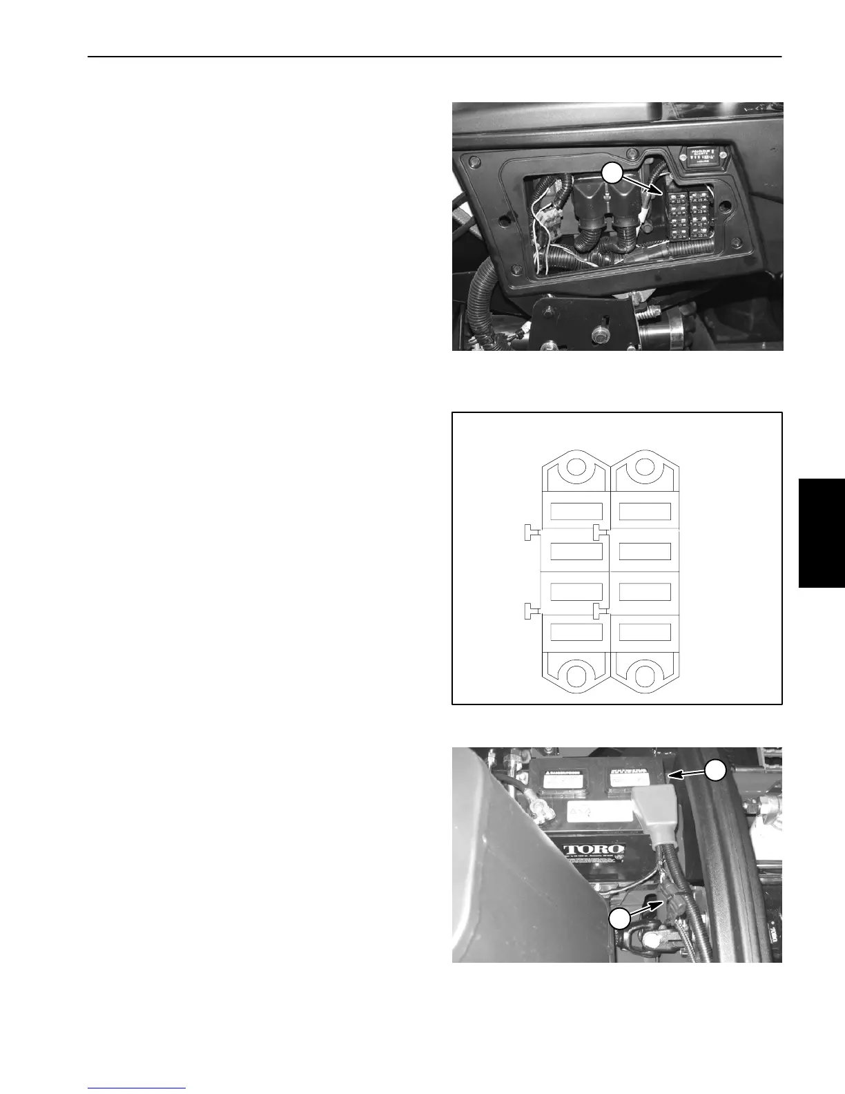
Fuses
Thefuseblock islocatedbehind thecontrolarm access
cover (Fig. 39).
In addition to the fuses in the fuse block, a 2 amp fuse
(F3) is included in the wire harness to protect the logic
power circuitfor theTEC controller. Thisfuse residesin
a fuse holder near the battery (Fig. 41).
Identification and Function
UseFigure40toidentifyeachindividualfuseanditscor-
rectamperage.FusesforyourGroundsmasterhavethe
following function:
F1 -- 1 (15 Amp): Protects starter circuit power sup-
ply.
F1 -- 2 (10 Amp): Protects main power supply.
F1 -- 3 (10 Amp): Protects power supply for head-
lights.
F1 -- 4 (10 Amp): Protects power supply for power
point.
F2 -- 1 (7.5 Amp): Protects power supply for TEC
controller outputs.
F2 -- 2 (7.5 Amp): Protects power supply for TEC
controller outputs.
F2 -- 3 (7.5 Amp): Protects power supply for TEC
controller outputs.
F2 -- 4 (15 Amp) (if equipped):Protects powersup-
ply for the optional air ride operator seat.
Testing
Turn ignition switch to the ON position (do not start en-
gine). With the fuse installed in the fuse block, use a
multimetertoverifythat12VDC existsatbothoftheter-
minal test points on the fuse. If 12 VDC exists at one of
thefusetestpointsbutnotattheother,the fuseisfaulty.
If necessary, remove fuse from the fuse block to check
fuse resistance. Fuse should have continuity between
the fuse terminals.
1. Fuse block
Figure 39
1
Figure 40
4
3
2
1
OPTIONAL
7.5A
10A
10A
10A
15A
F1 F2
4
3
2
1
7.5A
7.5A
1. Battery 2. Fuse F3
Figure 41
1
2
Electrical
System

 Loading...