Groundsmaster 4300--D Page 5 -- 33 Electrical System
Main Power and Glow Relays
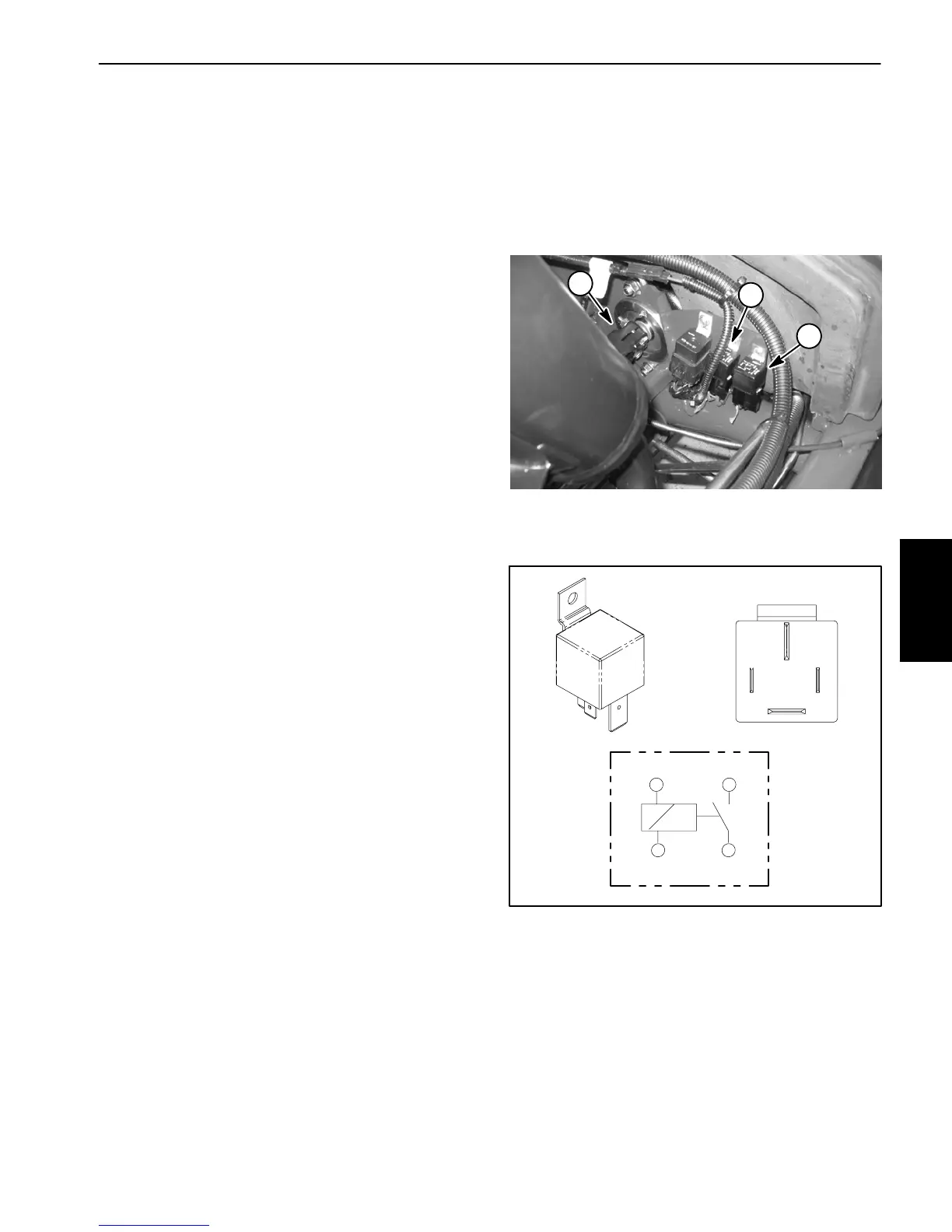
The Groundsmaster electrical system includes two
identical relaysfor current control. Themain power and
glow relays are attached to a frame bracket under the
hood next to the hydraulic pump drive shaft (Fig. 36).
Relays can be identified by a tag on the wire harness.
The main power relay is used to provide current to the
TEC controller, headlights, power point and optional
electric equipment. When the ignition switch is in the
RUN or START position, the main power relay is ener-
gized.
The glow relay is used to provide current to the engine
glow plugs when energized by the TEC controller. The
controller controls and monitors the operation of the
glow relay. The glow relay and its circuit wiring should
be tested asa controller output withthe Diagnostic Dis-
play before disconnecting and testing the relay (see
Special Tools and Tr oubleshooting in this chapter).
Testing
1. Park machine on a level s urface, lower cutting
decks, stop engine, apply parking brake and remove
key from ignition switch.
2. Open hood to gain access to relay.
3. Locate relay and disconnect the machine wire har-
ness connector from the relay. Remove relay from ma-
chine for easier testing.
NOTE: Prior to taking small resistance readings with a
digital multimeter, short the meter test leads together.
The meter will display a small resistance value (usually
0.5 ohms or less). This resistance is due to the internal
resistanceofthe meterandtestleads.Subtractthisval-
uefrom fromthemeasured valueofthecomponent you
are testing.
4. Verify coil resistance between terminals 85 and 86
with a multimeter (ohms setting) (Fig. 37). Resistance
should be approximately 72 ohms.
5. Connectmultimeter(ohmss etting)leadstorelayter-
minals 30 and 87. Ground terminal 86 and apply +12
VDCtoterminal85.Therelayshouldhavecontinuitybe-
tweenterminals30and87as +12VDCisapplied toter-
minal 85.The relay should nothave continuity between
terminals30and 87as+12VDCis removedfromtermi-
nal 85.
6. Disconnectv oltage andtestleads fromtherelay ter-
minals. Replace relay if necessary.
7. Secure relay to machine and connect machine wire
harness connector to r elay.
8. Lower and secure hood.
1. Pump drive shaft
2. Main power relay
3. Glow relay
Figure 36
1
3
2
Figure 37
86 87
85 30
85 86
87
30
Electrical
System

 Loading...