Groundsmaster 4300--D Page 5 -- 31 Electrical System
Mow/Transport Switch
Themow/transportswitchisanormallyclosedproximity
switchthat openswhenthe mowspeedlimiter isplaced
inthetransportposition.Theswitchmountstoabracket
on thefootrest platform.The sensing platefor the mow/
transport switch is the mow speed limiter. The mow/
transport switch is used as an input for the TEC
controller.
Testing
1. Before disconnecting the mow/transport switch for
testing,the switch andits circuitwiringshould betested
as a TEC controller input with the Diagnostic Display
(see Diagnostic Display in the Troubleshooting section
ofthischapter).IftheD iagnosticDisplayverifiesthatthe
mow/transport switch and circuit wiring are functioning
correctly, no furtherswitch testingis necessary.If,how-
ever, the Diagnostic Display determines that the mow/
transport s witch and circuit wiring are not functioning
correctly, proceed with testing procedure.
2. Turn ignition switch to the ON position ( do not start
engine) and check LED on cable end of mow/transport
switch (Fig. 33). LED should be illuminated when the
mow speed limiter is in the MOW position. The LED
should not be illuminated when the limiter is in the
TRANSPORT position.
3. Ifthemow/transport switchLEDdidnotfunctioncor-
rectly:
A. Make surethat themow/transportswitch isprop-
erly adjusted (see Mow/Transport Switch in the Ad-
justments section of this chapter). If necessary,
adjust switch and return to step 2 above.
B. Make sure ignition switch isOFF and disconnect
the mow/transport switch connector from machine
wire harness.
C. Verify that the machine wire harness connector
terminal for black wire is closed (continuity) to
ground.
D. Turn ignition switch to the ON position (do not
start engine) and verify with a multimeter that ma-
chine wire harness connector terminal for pink wire
has system voltage (12 VDC) present.
E. If black wire is closed to ground, pink wire has
systemvoltagepresentandswitchLEDdidnotfunc-
tion,replace mow/transportswitch.Adjust switchaf-
ter installation (see Mow/Transport Switch in the
Adjustments section of this chapter).
4. If the mow/transport switch tests correctly and a c ir-
cuitproblemstillexists,checkwireharness(seeElectri-
cal Schematic and Circuit Drawings in Chapter 8 --
Foldout Drawings).
5. Makesurethatmow/transportswitchisconnectedto
wire harness when testing is complete.
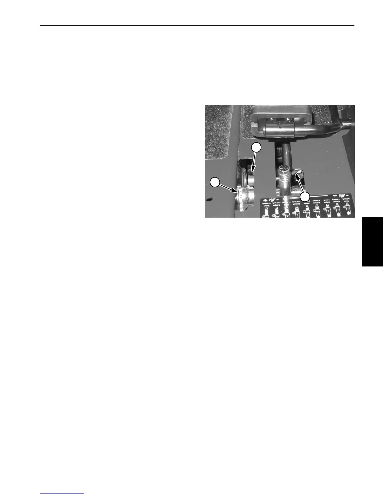
1. Mow speed limiter
2. Mow/transport switch
3. Switch cable
Figure 33
1
2
3
Electrical
System

 Loading...