Groundsmaster 4300--DHydraulic System Page 4 -- 100
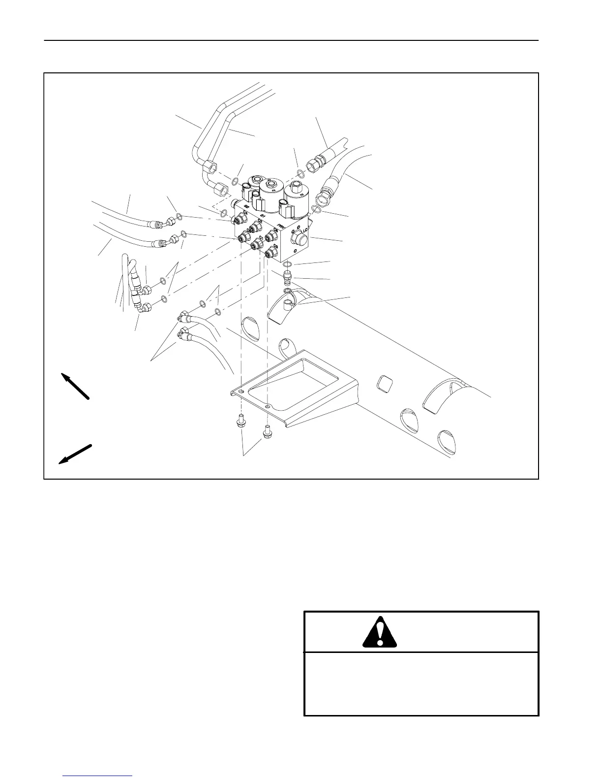
Lift Control Manifold
1. Lift control manifold
2. Flange head screw (2 used)
3. O--ring
4. Hydraulic hose
5. Hydraulic hose
6. Hydraulic hose
7. Hydraulic hose
8. Hydraulic hose
9. Hydraulic hose
10. Hydraulic tube
11. Hydraulic tube
12. O--ring
13. O--ring
14. Diagnostic fitting
15. O--ring
16. Hydraulic hose
17. Dust cap
Figure 90
FRONT
RIGHT
2
3
6
8
9
10
11
13
1
5
7
12
14
15
16
4
3
3
12
12
17
Removal (Fig. 90)
1. Parkthemachineonalevelsurface,engageparking
brake, lower cutting decks and stop engine. Remove
key from the ignition switch.
2. Read the General Precautions for R emoving and
Installing Hydraulic System Components at the begin-
ning of the Service and Repairs section of this chapter.
3. Locate hydraulic liftcontrol manifold thatis attached
to frame bracket under the front platform.
4. Label all hydraulic connections for assembly pur-
poses. Thoroughly clean hydraulic connections prior to
loosening hydraulic lines.
CAUTION
Beforeopeninghydraulicsystem,operateallhy-
draulic controls to relieve system pressure and
avoid injury from pressurized hydraulic oil. See
RelievingHydraulicSystemPressurein theGen-
eral Information section of this chapter.

 Loading...