Groundsmaster 4300--DPage 5 -- 10Electrical System
Verify Diagnostic Display Output Functions
The Diagnostic Display also has the ability to detect
which output solenoids or relays are turned on by the
TECcontroller. Thisis aquick wayto determineifama-
chine malfunction is electrical or hydraulic.
NOTE: Anopenoutput(e.g.anunpluggedconnectoror
a broken wire) cannot be detected with the Diagnostic
Display.
1. Park machine on a level surface, lower the cutting
decks, stop the engine and engage the parking brake.
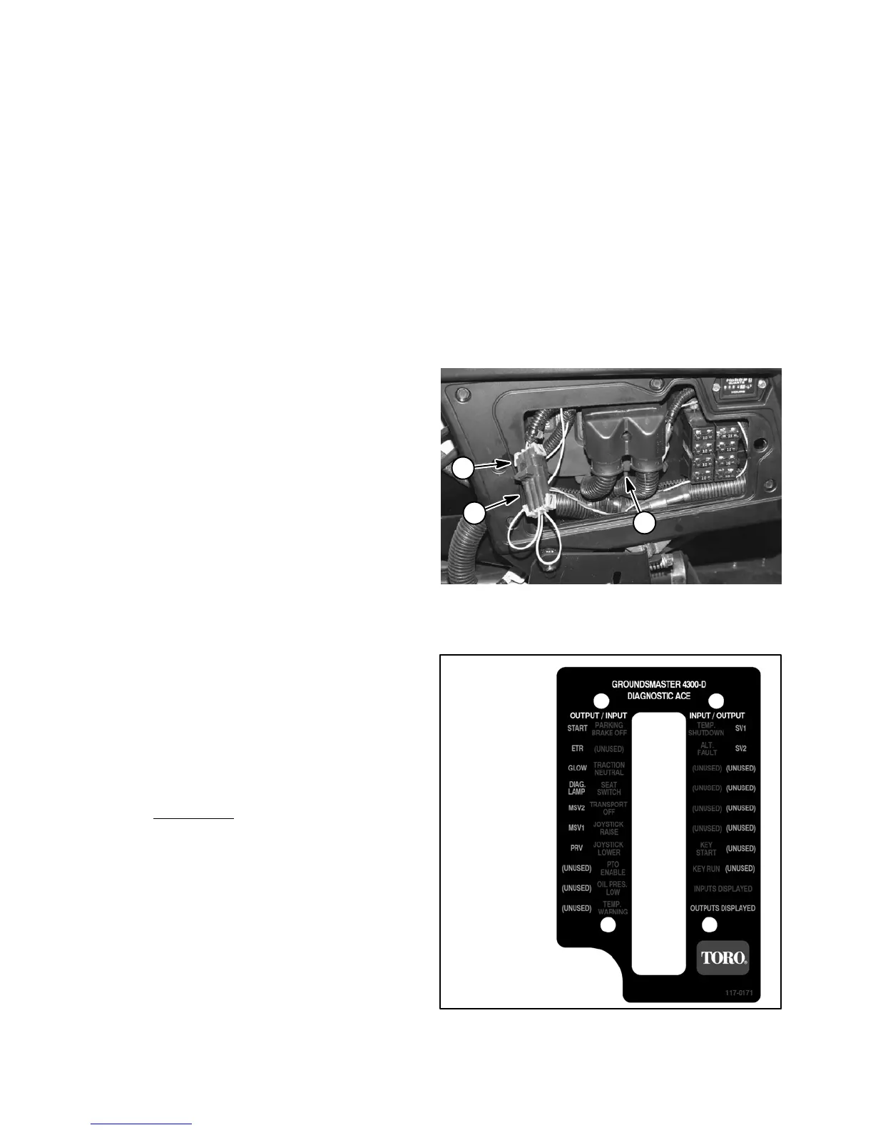
2. Open control panel cover. Locate wire harness and
connectors near TEC controller. Carefully unplug loop-
back connector from harness connector (Fig. 12).
3. ConnecttheDiagnosticDisplayconnectortothehar-
nessconnector.Makesurecorrectoverlaydecalisposi-
tioned on the D iagnostic Display (Fig. 13).
4. Turn the ignition switch to the RUN position.
NOTE: The red texton the overlay decal refers tocon-
troller inputs and the green text refers to controller out-
puts.
5. The green “OUTPUTS DISPLAYED” LED, on lower
right columnof theDiagnosticDisplay, shouldbe illumi-
nated. If “INPUTS DISPLAYED” LED is illuminated,
press the toggle button on the Diagnostic Display to
change the LED to “OUTPUTS DISPLAYED”.
NOTE: It may be necessary to toggle between “IN-
PUTSDISPLAYED”and“OUTPUTSDISPLAYED”sev-
eraltimes toperformthe followingstep.To changefrom
inputstooutputs,presstogglebuttononce.Thismaybe
done as often as required. Do not press and hold
toggle button.
6. Sit on seat, start engine and attempt to operate the
desiredfunctionofthemachine.Theappropriateoutput
LED’sshould illuminate onthe Diagnostic Displayto in-
dicatethatthe TECcontrolleris turningonthatfunction.
NOTE: Ifthe “DIAG.LAMP
”output LEDis blinking,this
indicates that the TEC controller has detected a fault
during machine operation. Refer to Diagnostic Light in
this section for information on retrieval and clearing of
controller faults.
A. IfthecorrectoutputLED’sdonotilluminate,verify
thattherequired inputswitchesarein thenecessary
positions to allow that function to occur (see TEC
Controller Logic Chart in this s ection). Verify correct
switch function.
B. If the output LED’s are on as specified, but the
machine does not function properly, consider that
the controller is operating correctly and a problem
existswithsomeothercomponent.Inspectelectrical
components and circuit for the affected function.
Also, suspecta non-electrical problem(e.g. hydrau-
lic component problem). Repair as necessary.
C. If each input switch is in the correct position and
functioning correctly, but the output LED’s are not
correctlyilluminated,thisindicates acontroller prob-
lem. If this occurs, contact your Toro Distributor for
assistance.
7. After output function testing is completed, discon-
nect the Diagnostic Display from wire harness. Plug
loopbackconnector intoharnessconnector.Installcon-
trol panel cover.
1. TEC controller location
2. Loopback connector
3. Harness connector
Figure 12
1
2
3
Figure 13
OVERLAY
DIAGNOSTIC
DISPLAY
117--0171

 Loading...