Groundsmaster 4300--DHydraulic System Page 4 -- 70
9. Loosen and remove two (2) carriage screws (item
12) and flange nuts (item 15) thatsecure pump support
bracket (item 8) to frame.
10.Remove two (2) flange screws (item 3) and flange
nuts (item 9) that secure traction pump flange to ma-
chine frame.
IMPORTANT: Make sure to not damage machine
components while removing the pump assembly.
11.Carefully lift pump assembly from the machine.
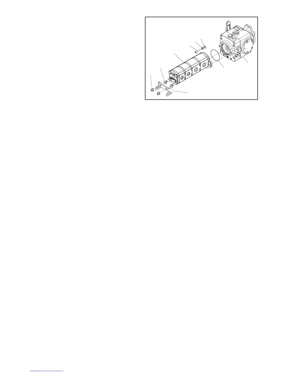
12.Separate traction and gear pumps (Fig. 70):
A. Remove two (2) socket head screws, lock wash-
ers and flat washers that secure gear pump to trac-
tion pump.
B. Remove gear pump from traction pump. Locate
and discard O--ring from between pumps.
C. Ifnecessary,removetwo(2)locknutsthatsecure
pumpsupportbrackettogearpump.Removebrack-
et and two (2) flat washers from gear pump.
13.If necessary, remove hydraulic fittings from pumps.
Note orientation of fittings for assembly purposes.
14.Remove and discard all O--rings from removed hy-
draulic lines and fittings.
Installation (Fig. 67)
1. Iffittings wereremovedfrompumps,lightlylubricate
newfittingO--ringswithcleanhydraulicoil.Installfittings
with O--rings to the pumps (see Hydraulic Fitting Instal-
lationintheGeneralInformationsectionofthischapter).
Orientate fittings as noted during removal.
2. Assemble traction and gear pumps (Fig. 70):
A. Lubricate and position new O--ring between
pumps.
B. Position gear pump to traction pump and secure
with two (2) socket head screws, lock washers and
flat washers.
C. If pump support bracket was removed from gear
pump, fitflat washersand bracket togear pumpand
secure with two (2) lock nuts.
IMPORTANT: Make sure to not damage machine
components while installing the pump assembly.
3. Carefully lower pump assembly to machine frame.
4. Secure pump assembly to machine frame with two
(2) flange screws and flange nuts.
1. Traction pump
2. O--ring
3. Flat washer (2 used)
4. Lock washer (2 used)
5. Socket screw (2 used)
6. Gear pump
7. Flat washer (2 used)
8. Pump support bracket
9. Lock nut (2 used)
Figure 70
6
5
7
3
1
2
8
4
9
5. Secure pump support bracket to inside of frame
bracket with two (2) carriage screws (item 12) and
flange nuts (item 15).
6. Install hydraulic hoses to fittings on pump assembly
in positions noted during removal (see Hydraulic Hose
andTube InstallationintheGeneralInformationsection
of this chapter).
7. Connect machine wire harness electrical connector
to traction neutral s witch.
8. Secure traction cable assembly to traction pump
(Fig. 69):
A. Positiontractioncableassemblytopumpassem-
bly.
B. Secure traction lever bracket (item 12 in Fig. 69)
topumpleverwithcapscrews(items7and13inFig.
69) and lock nut (item 8 in Fig. 69).
C. Secure lever damper (item 14 in Fig. 69) to trac-
tion cable bracket with flange nut (item 4 in Fig. 69).
D. Secure traction cable to traction cable bracket
(item 6 in Fig. 69) with jam nuts.
9. Install hydraulic pump drive shaft ( see Hydraulic
Pump Drive Shaft Installation in this section).
10.Checkoillevel inhydraulicreservoirandaddcorrect
oil if necessary.
11.Follow H ydraulic System Start--up procedures (see
Hydraulic System Start--up in this section).
12.Check traction drive for neutral and traction neutral
switch operation. Adjust if necessary.

 Loading...