Groundsmaster 4300--DHydraulic System Page 4 -- 88
CrossTrax
TM
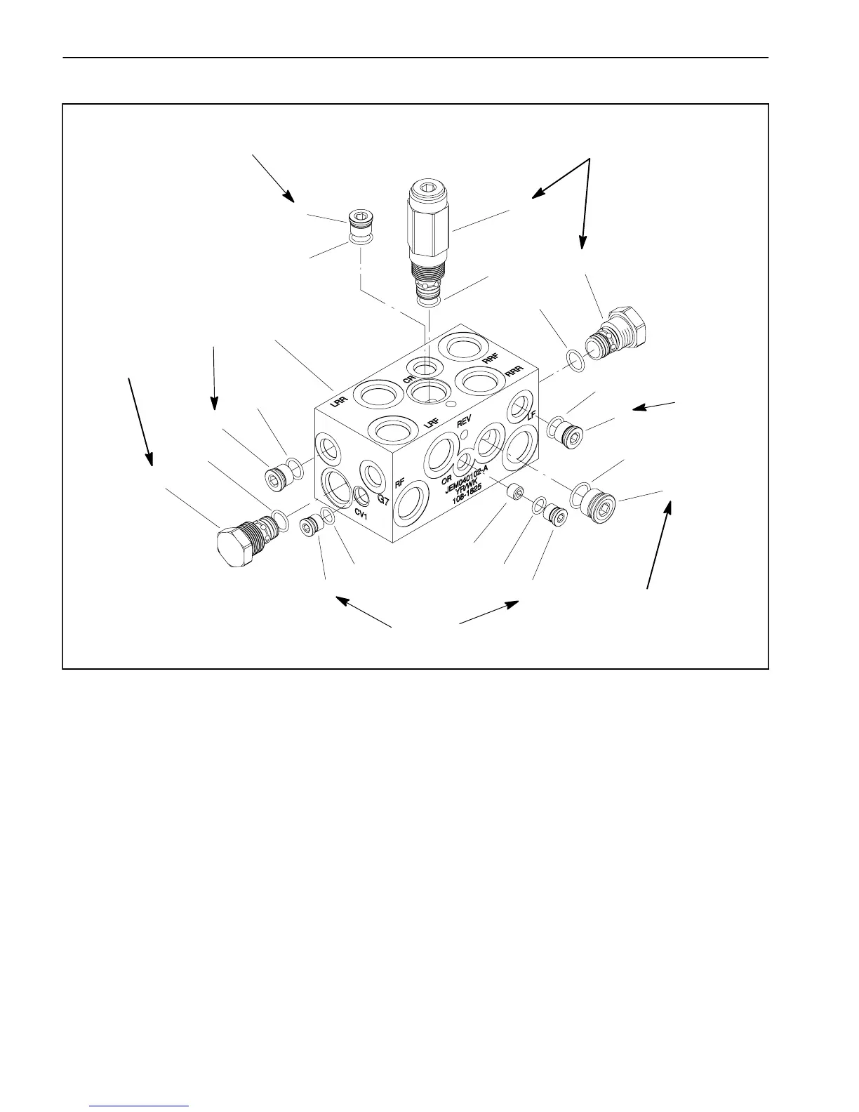
AWD Manifold Service
1. AWD manifold
2. O--ring
3. Plug (zero leak #6)
4. Seal kit
5. Check valve
6. Plug (zero leak #4)
7. O--ring
8. Orifice (.040)
9. Plug (zero leak #8)
10. O--ring
11. Seal kit
12. Bi--Directional relief valve
Figure 78
4
3
1
2
9
10
11
8
5
6
7
12
2
2
3
3
4
5
6
7
(33 N--m)
25 ft--lb
(33 N--m)
25 ft--lb
120 in--lb
(13.5 N--m)
(62 N--m)
46 ft--lb
220 in--lb
(24.8 N--m)
220 in--lb
(24.8 N--m)
220 in--lb
(24.8 N--m)
Forcontrolmanifoldserviceprocedures,seeDeckCon-
trol Manifold Service in this section. Refer to Figure 78
for CrossTrax
TM
AWD control manifold cartridge valve
installation torque.
NOTE: Adjustment of Bi--Directional Relief Valve (item
12) is NOT recommended.
NOTE: The CrossTrax
TM
AWD control manifold uses
several zero leak plugs. These plugs have a tapered
sealing surface on the plug head that is designed to re-
sist vibration induced plug loosening. The zero leak
plugs also havean O--ring to provide a secondary seal.
If zero leak plug removal is necessary, lightly rap the
plug head using a punch and hammer before using an
allen wrench to remove the plug: the impact will allow
plug removal with less chance of damage to the socket
head of the plug. When installing plugs into the control
manifold,torqueplugstothevaluesidentifiedinFigures
78.

 Loading...