Groundsmaster 4300--D Page 5 -- 29 Electrical System
Traction Neutral Switch
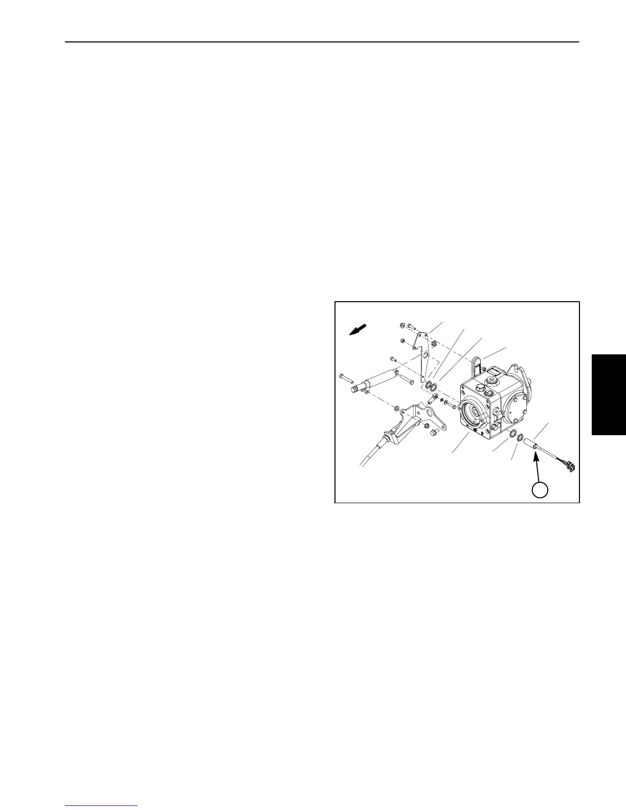
The traction neutral switch is anormally open proximity
switch that closes when thetractionpedal is in the neu-
tralposition.Theswitchmountstoabracketonthetrac-
tion pump (Fig. 31). The sensing plate for the traction
neutralswitchisthetractionleverbracketthatissecured
to the pump control arm. The neutral switch is used as
an input for the TEC controller.
Testing
1. Before disconnecting the traction neutral switch for
testing,the switch andits circuitwiringshould betested
as a TEC controller input with the Diagnostic Display
(see Diagnostic Display in the Troubleshooting section
ofthischapter).IftheD iagnosticDisplayverifiesthatthe
traction neutral switch and circuit wiring are functioning
correctly, no furtherswitch testingis necessary.If,how-
ever,theDiagnosticDisplaydeterminesthatthetraction
neutralswitchand circuitwiringare notfunctioningcor-
rectly, proceed with testing procedure.
2. Turn ignition switch to the ON position ( do not start
engine) and check LED on cable end of neutral switch
(Fig. 31). LED should be illuminated when the traction
pedal is in the neutral position.
3. WiththeignitionswitchstillintheONposition(donot
startengine),presstractionpedaloutoftheneutralposi-
tionand checkLED oncableend ofneutral switch.LED
should not be illuminated when the traction pedal is
not in the neutral position.
4. If the neutral switch LED did not function correctly:
A. Makesurethatneutralswitchisproperlyadjusted
(seeTractionNeutralSwitchintheAdjustmentss ec-
tion of this chapter). If necessary, adjust switch and
return to step 2 above.
B. Make sure ignition switch isOFF and disconnect
the traction neutral switch connector from the ma-
chine wire harness.
C. Verify that the machine wire harness connector
terminal for black wire is closed (continuity) to
ground.
D. Turn ignition switch to the ON position (do not
start engine) and verify with a multimeter that ma-
chine wire harness connector terminal for pink wire
has system voltage (12 VDC) present.
E. If black wire is closed to ground, pink wire has
systemvoltagepresentandswitchLEDdidnotfunc-
tion,replacetractionneutralswitch.Adjustswitchaf-
ter installation (see Traction Neutral Switch in the
Adjustments section of this chapter).
5. Iftheneutralswitchtestscorrectlyandacircuitprob-
lemstillexists,checkwireharness(seeElectricalSche-
matic and Circuit Drawings in Chapter 8 -- Foldout
Drawings).
6. Make sure that traction neutral switch is connected
to wire harness when testing is complete.
Figure 31
FRONT
1. Traction pump
2. Traction neutral switch
3. Traction lever bracket
4. Pump control arm
5. Jam nut (2 used)
6. Lock washer (2 used)
7. Switch LED location
2
3
4
5
1
6
7
6
5
Electrical
System

 Loading...