Groundsmaster 4300--D Hydraulic SystemPage 4 -- 91
Removal (Fig. 79)
1. Parkthemachineonalevelsurface,engageparking
brake, lower cutting decks and stop engine. Remove
key from the ignition switch.
2. Read the General Precautions for R emoving and
Installing Hydraulic System Components at the begin-
ning of the Service and Repairs section of this chapter.
3. Tiltoperatorseatandengageseatproptoretainseat
in the raised position.
4. Locate hydraulic deck control manifold.
5. Label all hydraulicand electrical connections foras-
sembly purposes. Thoroughly clean hydraulic connec-
tions prior to loosening hydraulic lines.
CAUTION
Beforeopeninghydraulicsystem,operateallhy-
draulic controls to relieve system pressure and
avoid injury from pressurized hydraulic oil. See
RelievingHydraulicSystemPressurein theGen-
eral Information section of this chapter.
6. Disconnect hydraulichoses and linesfrom fittingsin
manifold. Allow lines to drain into a suitable container.
Remove and discard O--rings from fittings.
7. Putcapsorplugsondisconnectedhosesandfittings
to prevent contamination.
8. Unplug wire harness leads from solenoid coils on
manifold.
9. Remove three (3) flange head screws that secure
manifold to machine frame.
10.Remove manifold block from machine.
11.Ifnecessary,removehydraulicfittings frommanifold
(Fig. 80). Discard any removed O--rings.
Installation (Fig. 79)
1. If fittings were removed from deck control manifold,
lubricate and place new O--rings on fittings (Fig. 80).
Install fittingsinto manifold (seeHydraulic FittingInstal-
lationintheGeneralInformationsectionofthischapter).
Torque fittings to values identified in Figure 80.
2. Position deck controlmanifold to frame.Install three
(3) flange head screws but do not fully tighten.
3. Remove caps and plugs from disconnected lines
and fittings.
4. Lubricate and install new O--rings on manifold fit-
tings. Connect hydraulic lines to hydraulic fittings on
manifold and properly tighten all connections (see Hy-
draulic Hose and Tube Installation in the General Infor-
mation section of this chapter).
5. Secure hydraulic manifold to frame by tightening
three (3) flange head screws.
6. Plug wire harness leads to solenoid coils on man-
ifold.
7. Lower and secure operator seat.
8. Checkoillevel inhydraulicreservoirandaddcorrect
oil if necessary.
9. Follow Hydraulic System Start--up procedures (see
Hydraulic System Start--up in this section).
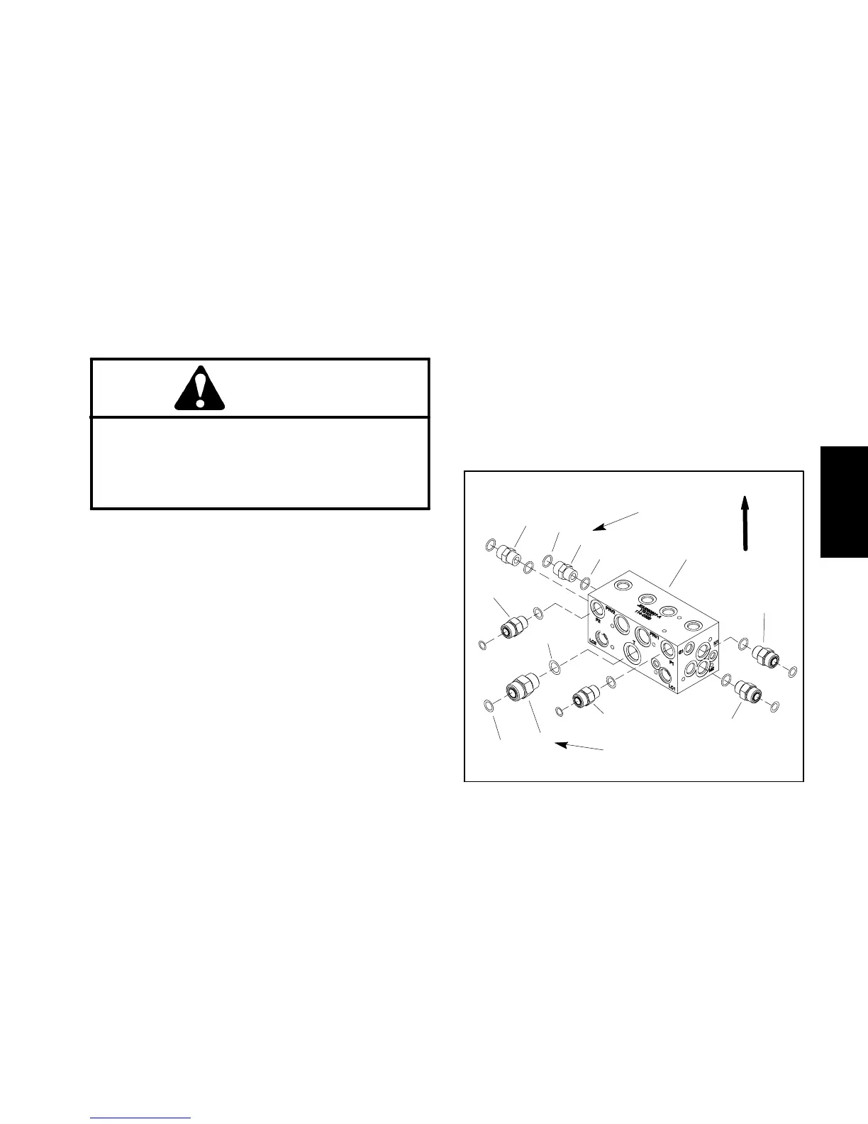
1. Deck control manifold
2. Hydraulic fitting (6 used)
3. O--ring
4. O--ring
5. Hydraulic fitting
6. O--ring
7. O--ring
Figure 80
1
5
2
3
4
7
6
2
2
2
2
2
UP
75 ft--lb
(101 N--m)
81 to 99 ft--lb
(110 to 134 N--m)
Hydraulic
System

 Loading...