Groundsmaster 4300--DPage 5 -- 38Electrical System
Hydraulic Solenoid Valve Coil
The Groundsmaster 4300--D hydraulic system uses
severalhydraulicsolenoidvalvecoilsforsystemcontrol.
The deck control manifold includes two (2) solenoid
valves (Fig. 46) and the lift control manifold includes
three (3) solenoid valves (Fig. 47). When the solenoid
coils are energized, hydraulic valve shift occurs to con-
trol hydraulic flow. Testing of the coils can be done with
the coil installed on the hydraulic valve.
Testing
1. Before disconnecting solenoid valve coils, test the
solenoids and their circuit wiring as TEC controller out-
putswiththeDiagnosticDisplay(seeDiagnosticDisplay
in the Troubleshooting section of this chapter). If the
DiagnosticDisplayverifiesthatsolenoidcoilsandcircuit
wiringarefunctioningcorrectly,nofurthertestingisnec-
essary.
2. If the Diagnostic Display determines that coils and
circuitwiringarenotfunctioningcorrectly,parkmachine
onlevelsurface,lowercuttingdecks,stopengine,apply
parking brake and remove key from ignition switch.
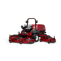
3. To gain access to deck control manifold (Fig. 46),
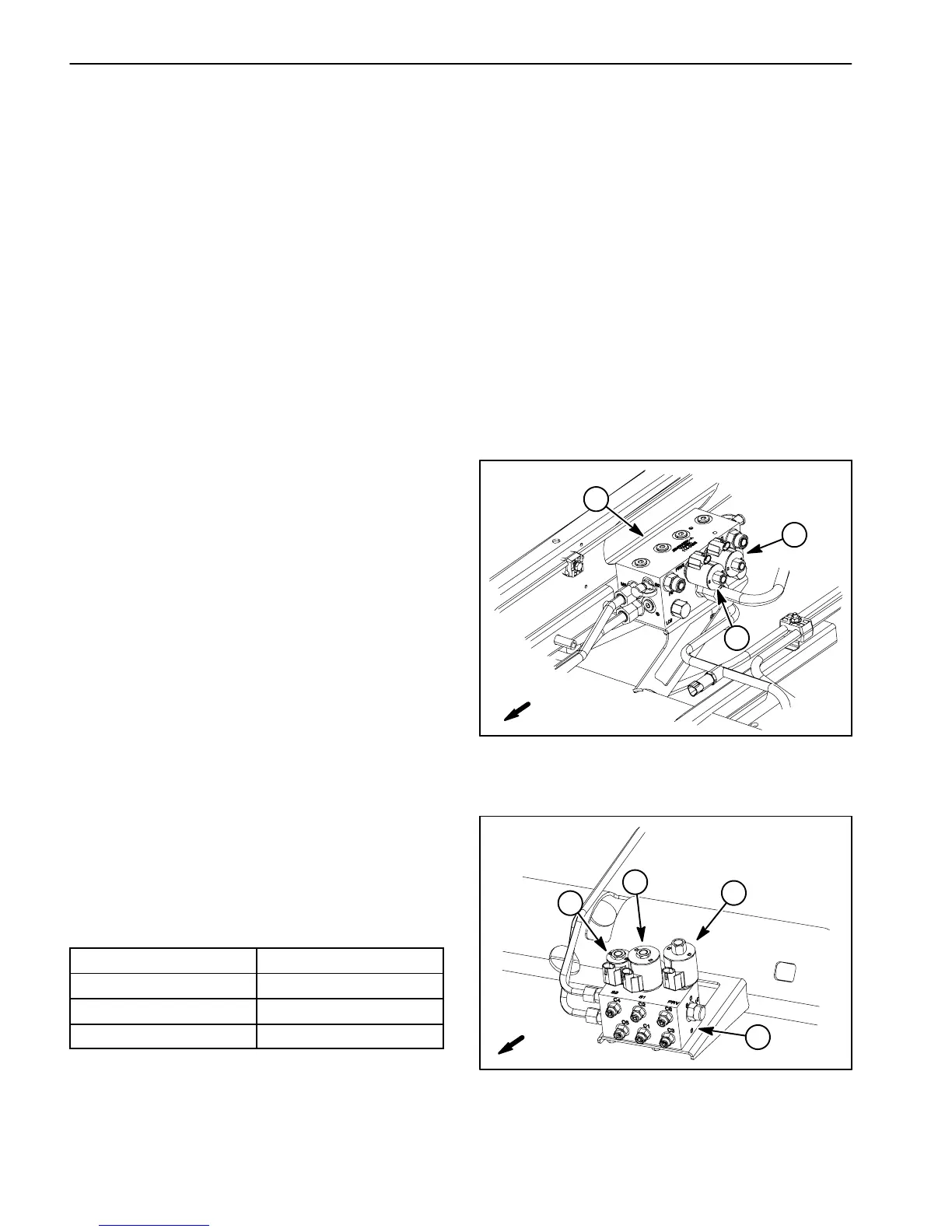
raise and prop the operator seat. Access to the lift con-
trol manifold (Fig. 47) can be obtained by removing the
operator floor plate.
4. Disconnect harness electrical connector from hy-
draulic solenoidvalve coil thatis to betested (Fig. 46or
47).
NOTE: Prior to taking small resistance readings with a
digital multimeter, short the meter test leads together.
Themetermaydisplayasmallresistancev alue(usually
0.5 ohms or less). This resistance is due to the internal
resistanceofthe meterandtestleads.Subtractthisval-
ue from the measured value of the component you are
testing.
5. Using a multimeter (ohms setting), measure resis-
tancebetween thetwoconnector terminalson thesole-
noid valve coil. The resistance for the solenoid coils is
identified below:
Solenoid Valve Coil
Resistance
PRV1 and PRV2 (deck) 7.1 ohms
SV1 and PRV (lift) 7.1 ohms
SV2 (lift) 8.7 ohms
6. If solenoid coil resistance is incorrect, replace sole-
noid (see Hydraulic Solenoid Valve Coil Removal and
Installation in the Service and Repairs section of this
chapter).
NOTE: The two (2) solenoid valve coils on the deck
control manifold (PRV1 and PRV2) are identical. Sole-
noidvalvecoilsSV1andPRVontheliftcontrolmanifold
are identical and are the same as those used on the
deck manifold. The remaining lift manifold coil (SV2) is
different.Toassistintroubleshooting,identicalcoilscan
be exchanged. If the problem follows the exchanged
coil,anelectricalproblemlikelyexistswiththecoil.Ifthe
problem remainsunchanged, something other thanthe
solenoid coil is the problem source (e.g. switch, circuit
wiring, hydraulic problem).
7. Connect wireharnesselectrical connectortothe so-
lenoid valve coil after testing is completed.
8. Lower and secure seat if deck control manifold was
accessed. Install operator floor plate if lift control man-
ifold was accessed.
1. Deck control manifold
2. PRV2 solenoid
3. PRV1 solenoid
Figure 46
1
3
2
FRONT
1. Lift control manifold
2. SV1 solenoid
3. SV2 solenoid
4. PRV solenoid
Figure 47
4
1
3
2
FRONT

 Loading...