Groundsmaster 4300--D Hydraulic SystemPage 4 -- 13
Mow Circuit
A four section gear pump is coupled to the piston (trac-
tion) pump. Gear pump sections (P1) and (P2) supply
hydraulic flow for the mow circuit. These gear pumps
take their suction from the hydraulic reservoir.
Thedeckcontrolmanifoldcontainstwo(2)independent
controlcircuitsforthefrontandrearcuttingdecks.Each
circuit is supplied by its own pump section. Pump sec-
tion (P1) supplies hydraulic power to the rear cutting
decks with circuit control by proportional relief valve
(PRV1), relief valve (RV1) and logic cartridge (LC1) in
the deck control manifold. Pump section (P2) supplies
thefrontcuttingdeckswithcircuitcontrolbyproportional
reliefvalve(PRV2),reliefvalve(RV2)andlogiccartridge
(LC2) in the deck control manifold. Both circuits share
manifoldportT,whichdrainstotheoilcooler,oilfilterand
hydraulic reservoir.
Cutting deck motors are equipped with a cross over re-
lief valve to prevent hydraulic component damage in
case a single cutting deck should s tall.
The machine controller uses inputs from various ma-
chineswitchestodeterminewhenthesolenoidsforpro-
portional relief valves (PRV1) and (PRV2) are to be
energized. Thecontroller also provides aslight delay in
activation of rear cutting decks.
PTO Not Engaged
Whenproportionalrelief valves(PRV1)and(PRV2) are
notenergized(PTOswitchintheOFFpositionorcutting
decksraised), flowfrom pumpsections (P1)and (P2)is
directedthroughtheunshiftedproportionalreliefvalves,
out the mow control manifold port T and then returns to
thehydraulicreservoirthroughtheoilfilterandoilcooler,
bypassing the deck motors. The manifold logic car-
tridges (LC1 and LC2) remain in the unshifted position
to prevent any return flow from the deck motors so the
motors will not rotate.
PTO Engaged (Fig. 11)
When proportional relief valve (PRV1) is energized by
thecontroller(PTOswitchintheONpositionandcutting
decks lowered), the proportional relief valve shifts and
prevents pump section (P1) flow through the valve.
Pump flowthat entered deckcontrol manifold portP1 is
then directed toward the rear cutting deck motors. Be-
cause logic cartridge LC1 is unshifted, circuit pressure
increases until manifold relief valve (RV1) is opened by
a manifold pilot piston. The shifted relief valve allows a
small amount of hydraulic flow to return to tank through
amanifoldsensingline.Thisflowpassesthroughanori-
ficewhichcausesa pressuredifferentialthatshiftslogic
cartridge LC1. The shifted LC1 allows circuit flow to ro-
tate the rear cutting deck motors. Return oil from the
deck motors is directed through the shifted logic car-
tridge(LC1),manifoldportT,oilcooler, oilfilterandthen
to thereservoir.Deck motor case drain leakage returns
directly to the hydraulic reservoir.
Mow circuit pressure for the rear cutting decks (pump
section P1) can be measured at deck control manifold
port G1.
The front cutting deck circuit operates the same as the
rear cutting deck circuit. Deck control manifold propor-
tional relief (PRV2), relief valve (RV2) and logic car-
tridge (LC2) are used to control the front cutting deck
circuit. Mow c ircuit pressure for the front cutting decks
(pump section P2) can be measured at deck control
manifold port G2.
Cutting Deck Circuit Relief
Maximum cutting deck circuit pressure is limited by the
proportional relief valves in the hydraulic control man-
ifold. The front deck circuit valve (PRV2) is set at 3500
PSI (241 bar) and the rear deck circuit valve (PRV1) is
set at 2500 PSI (175 bar).
When increased circuit resistance is met (e.g. a cutting
blade should strike an object), the pressure increase is
felt at the proportional relief valve. If circuit pressure
shouldexceedthereliefsetting,thevalvewillopentoal-
low circuit flowto return to tank through manifoldport T.
When circuit pressure lowers, the valve c loses to allow
flow to return to the deck motors.
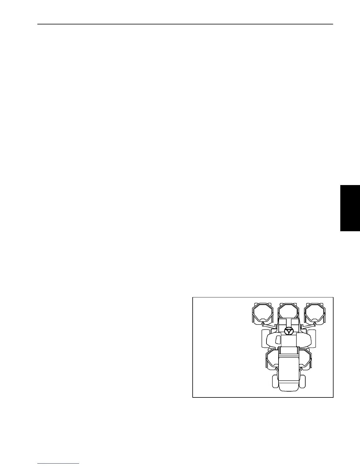
Figure 12
#4 #1 #5
#3#2
GROUNDSMASTER
4300--D CUTTING
DECK LOCATIONS
Hydraulic
System

 Loading...