Groundsmaster 4300--D Page 5 -- 25 Electrical System
PTO Switch
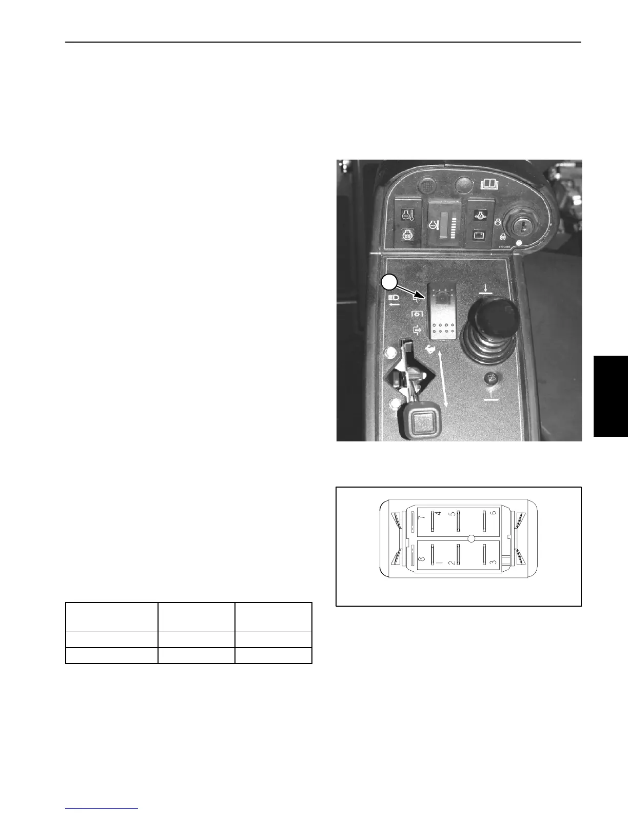
ThePTOswitch ismounted onthe controlpanel andal-
lows the cutting decks to operate when the front of the
switch is depressed. An indicator light on the switch
identifies when the PTO switch is engaged.
The TEC controller monitors the position of the PTO
switch (up or down). Using inputs from the PTO switch
andotherswitchesintheinterlocksystem,thecontroller
controls the energizing of the hydraulic solenoid valves
used to drive the cutting deck motors.
NOTE: To engage the PTO, the seat has to be occu-
pied, the mow speed limiter has to be in the mow posi-
tion and the c utting decks have to be fully lowered.
Testing
1. Before disconnectingthe PTOswitchfor testing,the
switch and its circuit wiring should be tested as a TEC
controller input with the Diagnostic Display (see Diag-
nostic D isplay in the Troubleshooting section of this
chapter). If the Diagnostic Display verifies that the PTO
switchandcircuitwiringarefunctioningcorrectly,nofur-
ther switch testing is necessary. If, however, the Diag-
nostic Display determines that the PTO switch and
circuitwiring arenot functioningcorrectly,proceedwith
test procedure.
2. Remove control arm covers to gain access to PTO
switch(seeControlArmDisassemblyintheServiceand
Repairs section of Chapter 6 -- Chassis).
3. Make sureignitionswitchis intheOFFposition.Dis-
connectw ireharnesselectricalconnectorfromthePTO
switch.
4. With the use of a multimeter (ohms setting), the
switch functions may be tested to determine whether
continuityexistsbetween thevariousterminalsforeach
switch position. The PTO switch terminals are marked
as shown in Figure 24. The circuitry of this switch is
shown in the chart below. Verify continuity between
switch terminals.
SWITCH
POSITION
NORMAL
CIRCUITS
OTHER
CIRCUITS
ON 2+3 5+6
OFF 2+1 5+4
5. Replace PTO switch if necessary.
6. If PTO switch tests correctly and circuit problem still
exists, check wire harness (see Electrical Schematic
andCircuit DrawingsinChapter 8 -- Foldout Drawings).
7. Connect wire harness electrical connector to the
PTO switch.
8. Install control arm cover to machine (see Control
Arm Assembly in the Service and Repairs section of
Chapter 6 -- Chassis).
1. PTO switch
Figure 23
1
Figure 24
BACK OF SWITCH
NOTE: PTOswitch terminals7 and 8are for theswitch
indicator light. Switch terminals 1, 4, 5 and 6 are not
used on Groundsmaster 4300--D machines.
Electrical
System

 Loading...