2GR-FE ENGINE MECHANICAL – ENGINE ASSEMBLY
EM–23
EM
REMOVAL
1. DISCHARGE FUEL SYSTEM PRESSURE
HINT:
See page FU-1.
2. DISCONNECT CABLE FROM NEGATIVE BATTERY
TERMINAL
3. PLACE FRONT WHEELS FACING STRAIGHT AHEAD
4. REMOVE FRONT WHEELS
5. REMOVE ENGINE UNDER COVER LH
6. REMOVE ENGINE UNDER COVER RH
7. REMOVE FRONT FENDER APRON SEAL RH
8. DRAIN ENGINE OIL (See page LU-4)
9. DRAIN ENGINE COOLANT (See page CO-5)
10. DRAIN AUTOMATIC TRANSAXLE FLUID (See page
AX-207)
11. REMOVE WINDSHIELD WIPER LINK ASSEMBLY
See page WW-9.
12. REMOVE COWL TOP PANEL OUTER SUB-
ASSEMBLY (See page ES-481)
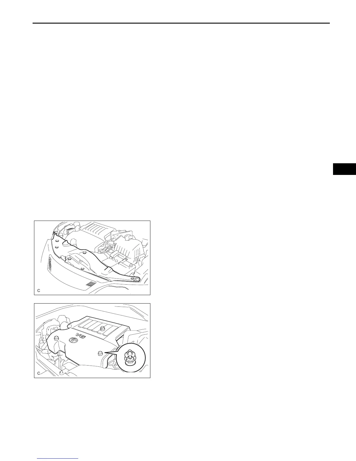
13. REMOVE COOL AIR INTAKE DUCT SEAL
(a) Remove the 7 clips and intake duct seal.
14. REMOVE V-BANK COVER SUB-ASSEMBLY
(a) Hold the front of the V-bank cover and raise it to
disengage the 2 clips on the front of the cover.
Continue to raise the cover to disengage the clip on
the rear of the cover and remove the cover.
NOTICE:
Attempting to disengage both front and rear
clips at the same time may cause the cover to
break.
15. REMOVE V-RIBBED BELT (See page EM-6)
A132967
A132968
 Loading...